First published in L&L Yearbook, 2016 issue.
Written by Harper product development engineer, Tony Donato
Plenty of articles and predictions in recent years are telling us that the age of intelligent packaging and printed electronics (PE) is just around the corner. I will not say what is coming, but I will relate what I have learned working with multiple universities, material and equipment suppliers and my own experimentation to see what is possible. This article is coming from the perspective of a generalist with a machinery maintenance and manufacturing background that has been working with the printing industry for over 25 years.
“Printed electronics is not simply putting conductive ink in a print station. There is a lot to consider”
Just to clarify, printed electronics is not new and has been around for decades; over 40 years ago I was taught how to chemically etch a circuit board. Membrane switches, used in common appliances such as microwave oven panels, are commonly printed on modern printing presses. Today, of the print processes, screen printing is used the most. Graphic printing processes are being viewed as tools to move electronics into flexible, wearable and lower cost applications. The majority of conferences I have attended are all discussing, exploring and wanting to move products into a roll to roll application (R2R) for various reasons, including cost reduction, market expansion and new product development.
To start off, it is important to understand the differences and similarities between graphics and functional printing using the flexographic process. Flexography has developed into a printing process that uses the precision placement and size of dots of different colors of ink to convince the human brain it is looking at a graphic printing that conveys an image that resembles reality. Graphic printing is literally in the eye of the beholder. In a few seconds a package’s graphics must catch the eye and win over a potential customer to buy the product. Once the purpose of the print job changes to a functional nature, the printed product has to respond and react not just to a consumer but also the laws of electrical physics.
In a simplified view of electrical functional printing, the printed image has to provide a conductive pathway where the electrical current can flow uninterrupted and with the functional properties needed. In many cases the functional properties will terminate at a voltage source (i.e. battery) and provide high amperage or it may be a dielectric insulation or some combination with multiple layers. In short, we are printing wires that need to allow the uninterrupted flow of electrical current or insulation to make a device function. The important point to understand is current – the flow of electrons – can only happen if the printed trace line is continuous with no pinholes or breaks, since electrons do not jump
When printing a conductor, the trace line width and thickness of a particular deposited conductive material (silver, carbon, graphene, conductive polymer etc) will determine the amount of current that can flow. All conductive inks are not the same. The base material itself determines the overall effectiveness and the ink film thickness needed to achieve minimum resistance. Very simply, silver ink is more conductive than a carbon-based inks (graphite, graphene etc), therefore more carbon ink needs to be deposited to provide the comparable electron flow or conductivity as metal-based inks. Translated into flexo terms, the BCM’s of the anilox roll required for silver ink (2 to 5bcm) is much less than the BCM’s need for carbon based ink (10 to 30bcm). The exact volume is be application dependent.
Printing with flexo
In printing conductors with flexo, instead of a graphic artist being concerned with eye appeal, the circuit designer is concerned with functionality and will calculate the required current load or needed properties for the device. That calculation will determine the criteria for what size printed trace line (cross sectional area) is needed. To complicate production planning, material costs are also considered in determining how to print. With silver at the higher end of ink costs, even though the amount carbon ink needed may be two or three times more, carbon ink may be the preferred choice and require using different anilox rolls than initially specified.
Think of extension cords. They come in different wire gage sizes and number of strands; the combination determines how much current can flow without damaging (melting) the cord. If the wire size is not sufficient for the required current flow, heat will be created. As many have learned the hard way, an extension cord sized to light a lamp is not the proper conductor for an air compressor, even if both rated for the same voltage. The good thing about R2R printed electronics is that circuits or devices typically are designed for low DC voltages and current (except in Electroluminescent (EL), where an AC electric field is required).
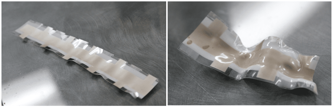
5 mil PET 4 layers for EL. Silver, Dielectric, Phosphor and Transparent conductor Toaster oven: Left 250F 10 minutes. Right 285F 10 minutes.
From the printer perspective all materials used must fit together and function in the daily environment required for the device. Inks and substrates must be compatible. Even the moisture content of a paper substrate needs to be considered because it could affect the performance of a printed device. Also with many inks, elevated drying temperatures may be needed to sinter (sintering can be thought of as a curing method for the ink) the metal particles of the ink into a continuous trace line. These elevated temperatures can damage conventional PET substrates and other plastics. I have curled and wrapped paper and ruffled PET trying to sinter the ink.
Not all functional printing entails conductive inks. For example, biomedical applications can be achieved with printing too. For example, sensors may be printed that absorb sweat so a chemical reaction may take place to detect a predictable physical outcome. These sensors can be used for monitoring a health factor.
In summary, the mindset needed to print PE or other functional devices needs to grasp all aspects of the printed job, not merely its appearance. The materials used will need to have functional properties. The functional properties will need to be tested using a multifunction electrical meter or test fixture and not a spectrodensitometer. To fully cure the ink and not damage the substrate sintering methods will have to be investigated that are not on the average flexo press. PE is not simply putting conductive ink in a print station. There is a lot to consider.
“Only around 1 to 2 percent of flexo printers doing a form of functional printing today, but those numbers will keep expanding as flexible and wearable device applications gain in popularity”
From the contacts I have met over the years in exploring PE, I landed on an electronic geek website, Sparkfun, which has a Bare Conductive ‘Touch Board’ to ‘turn touch into sound’. So a project was started to use the ‘Touch Board’ to create a hybrid device that used a flexo printed component combined with conventional microcontroller development platform. Hybrid devices are a realistic approach using conventional electronics that cannot be Flexo printed as the brains of the device. Flexo print can be used to build the traces as well as print the capacitive sensing ‘touch pad’. The ‘Touch Board’ can accept 12 inputs, so a conductive keyboard was laid out mathematically to match the locations of the inputs on the board and match the repeat of the plate cylinder of the Harper QD Flat Bed flexo print. Then a fixture had to be designed to couple the ‘Touch Board’ to the printed sensor touch pad.
The ‘Touch Board’ has 12 sound outputs that are MP3 formatted so different sounds can be loaded such that when the printed sensor is touched the preloaded sound is produced. One other neat feature of the board is the sensitivity of the capacitive sensor can be changed to make the board be a proximity sensor (1”) instead of merely a touch sensor.

The following picture shows all the components.
The QD Flatbed Flexo Printer was used to print conductive carbon inks for testing of trace line conductivity for touch sensor patterns. Testing different plate images and anilox engravings (120/15 XLT, 75/29 XOS and a 200/14.0 XOS) is easily done to find the best combination to work with a Touch Board combined w/ a print mounting fixture to demonstrate direct contact and proximity contact in a hybrid device w/ MP3 added sounds and a printed sensor pad.

In the picture, you can see an amber LED light illuminates (top of photo) when a key is touched and on the right picture the proximity of a hand activates the board. We made a video that shows the printing of the project and the project in action: https://www.youtube.com/watch?v=a8bgXCTBdIo.
If I had to guess, only around 1 to 2 percent of flexo printers are doing a form of functional printing today, but those numbers will keep expanding as flexible and wearable device applications gain popularity. Perhaps you will be one of the leaders in functional printing.
I need to thank Novacentrix, Sun Chemical and MacDermid for their help with the Touch Sensor project and Cal Poly, Clemson and Western Michigan for technical guidance.
To view the original L&L Yearbook article click HERE.


