
First published in Converting Quarterly, Quarter 2 2013 issue.
Written by Harper Technical Solutions team member, Sean Teuffler.
Abstract
If you are printing at high speeds using flexographic or gravure methods, you should be familiar with the revolutionary inking system known as the enclosed chamber. The creation of enclosed chambers makes an important contribution to the competitive edge it gives these printing processes. For the user, understanding how the chambers work allows you to maximize your print efficiency and achieve high output without creating print or process defects and without damaging anilox rolls.
Enclosed chambers are quite an advancement over prior ink train designs, and it is important to understand how the system evolved. The original two-roll method used a rubber meter roll to apply ink in a squeegee effect to the anilox roll surface. But this has the drawbacks of not being able to control the ink film when press speeds change, and it leaves the ink well exposed to the environment, leading to ink instability and a greater requirement for ink maintenance. The desire for faster speeds and greater ink-film control led to the invention and application of the reverse-angle doctor blade. This improvement controlled the ink film as a blade now sheared off excess ink from the anilox surface to deliver a consistent ink film. The remaining drawback was the ink exposure to the environment and the inability to prevent ink delivery to the edges of the anilox at higher speeds, in turn leading to ink spray and slinging – and the resulting print defects. The enclosed chamber system was introduced to address all of these issues. There have been many designs and varieties of the chamber over the years of development, but the core values of the chamber remain the same:
- Control the ink film
- Form a seal to the anilox-roll surface
- Limit ink exposure to the environment
- Remain effective as print speeds increase.
Getting a chamber system is only half the battle in ink delivery control. The rest involves understanding and maintaining the required machine-tolerance precision that makes chamber use an essential part of the printing process.
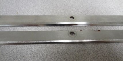
FIGURE 1. Clamps that have been rubbing and damaging anilox engraving
How does a printer make the most out of his or her enclosed chamber application? Chamber success begins by establishing the four processes of documented procedures, proper training and evaluation, component maintenance and establishment of workspace.
- Documented procedures include how to build a chamber, calibrate it, install it and clean it properly. Seek supplier input and have your team tailor the chamber to your particular design.
- Proper training and evaluation: Set up a system of mentors, expect employees to be able to demonstrate they can successfully build and clean each chamber.
- Maintaining components is critical. Worn parts must be replaced. Inspect frequently to keep the chambers sound.
- Workspace: Designate an area for chamber cleaning and building by establishing a cleaning station supplied with spare parts.
When we speak of getting the seal, it is not just referencing the seals on the ends of the chamber, but also how well the blades seat properly against the anilox. In many respects, the seals and the metal blades form a complex gasket to prevent ink leakage while maintaining a stable, ink-laden anilox surface.
How do we accomplish this seal and make it endure?
Keep Components Clean
As with any device, there are critical areas that must be in pristine condition to maximize desired performance criteria. For the enclosed chamber, the blade rest area is just such a critical point. This is the location where the installed blade should lay completely flat. Any ink debris along this area will prevent the blade from laying flat and will possibly cause a gap through which ink can travel. It also causes waves in the blade and creates uneven metering and wear detrimental to the life of the chamber, the anilox and the consistency of printing. Additionally, blade clamps must be clean, as dried ink will form gaps that liquid ink can pass through and create lengthy cleanups, lost ink and time.
Many chamber designs feature venting to prevent a vacuum from forming. Chamber ventilation is typically used when a chamber has an active pump displacement to drain the chamber, as opposed to a simple gravity drain. Failure to keep the vents free and functional causes the chamber to vacuum itself to the anilox, causing damage to the engraving.
Keep Components in Specification
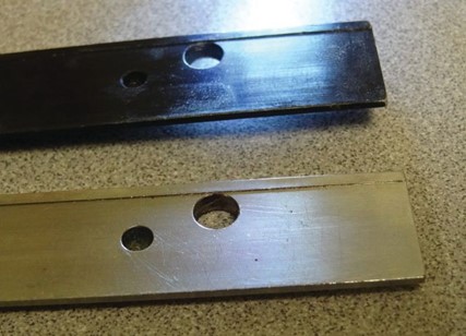
FIGURE 2. Bent and pitted components that will not perform to machine tolerance

FIGURE 2. Bent and pitted components that will not perform to machine tolerance
Now that we have established the importance of well-fit components to the whole package, we must look to how we clean those components. Ideally, any cleaning method should not modify or damage those components in the act of getting them clean. If you use a metal scraper, think of it as machining the surfaces it contacts. Abrasive pads also sand away material and become an unwanted machining process. Employ plastic scrapers or sponges to do the cleaning. In the long run, the chamber builds will be sound and repeatable, and cleanups are minimized because leaking is minimal. Training on how to properly clean them is essential to establish good habits.
Component handling matters. If chambers or clamps are dropped, they can become warped or bent. This takes these items completely out of their machine-tolerance specifications and renders them useless. If parts are lost, such as the bolts that help fasten the components together, make sure they are replaced with the correct threading and length. Windings inside thread holes can be stripped due to the wrong bolt being used. Recognize when the components have reached the end of their working life. If you see pitting, loss of metal and surface tolerance like rounded edges on components, then it is time to replace them. You will spend much more time and money addressing the constant leaking that can result than what it costs to get the proper components you need. Examples of components and related problems are shown in Figures 1-3.
Build the Chamber Correctly
When it is time for assembly, the parts you aren’t cleaning (such as blades and seals) are needed. Always make sure to use the correct blade and seal dimensions. Document this knowledge because, as time passes, mistakes can be made and can create havoc with chamber performance. Maintain instructions on how to assemble the chambers. Write these details to meet your particular needs and design requirements. Always supply training on assembly and inspection, and have the builds “signed off” on and inspected for quality.
For chambers requiring bolts, make sure that proper torque is applied after the blade and blade clamp are installed. Use a torque wrench to prevent thread-stripping of the chamber from overtightening. Also, start tightening from the center bolt and work your way out to the ends. If you tighten a bolt from one end or both ends, the blade will not be laying flat, but will buckle. There is only one right way to do this – to start from the center bolt and work your way to the ends. Examples of proper and improper builds are shown in Figures 4-5.
Keep Chambers Aligned
Chamber alignment allows the specifications you have worked so hard to maintain during cleaning and assembly to matter when you apply the chamber to the anilox surface. Alignment is directly involved with the support assembly that holds the chamber in press. Past excessive-pressure abuse and wear in the assembly components can lead to misalignment and poor chamber performance. Without the chamber lining up perfectly to the anilox, the seal and blades forming the complex gasket cannot, in turn, line up properly. Alignment – not over- pressurization of the chamber – is the answer to this problem.
Most chamber-support assemblies will go out of alignment at some point, even under the best of circumstances. Testing alignment is simple if you follow this procedure:
- Start with a clean chamber and metal blades of correct dimensions installed.
- Use metal blades for alignment, even if you don’t normally use them.
- Make sure the blades are laying
- Do not use seals at this point – they may interfere with the blades laying
- Install the chamber as you normally would.
- Bring the chamber up to but not where the blades are touching the anilox, and check with a bubble level to ensure – at least in a coarse fashion – that the chamber is square and level
- If your bubble is centered, go ahead and bring the chamber in to the anilox itself, just enough to where the blades are lightly touching the anilox surface.
- Use a gap gauge – 0020 in. – to check the fit between the blades and anilox. Check top and bottom, both ends and center. If all is well, you should get a “snug” response from the gauge. If something is amiss, you will find uneven responses from the gauge. If all is square, back out on the chamber and install plastic blades if you normally use them, install the seals and then you are ready to go.
Examples of misalignment
One blade is touching the anilox and the other is not, indicating an “overbite” by the chamber; the center portion of the blade lengths are touching the anilox but the end portions are not. This indicates the chamber is warped and vice versa; if the chamber is skewed axially, you might find a tight fit for the gauge in one set of opposite corners while being completely free in the other set.
Checking alignment will firmly identify problems either with a warped chamber or fatigued or damaged support-assembly components. Address these items immediately, or many problems with anilox wear, poor print performance and leaking will arise.

FIGURES 4-5. Proper enclosed chamber build (left) and improper build (right)
Mechanical or Pneumatic Issues
The mechanism of applying the chamber to the anilox must be sound. Does the mechanism pre-load the chamber without any adjustment That might be a sign something is not working properly. Can you activate and deactivate the chamber with the chamber going to the proper position evenly and fully every time If not, you cannot guarantee an even load.
The components of the chamber engagement system can fail as well, so they must be maintained and inspected. For pneumatic systems, confirm that the air supply is clean and at the proper pressure and airflow (in cfm) at all times, or performance will be inconsistent at the minimum. If you use an active displacement pump to remove ink from the chamber, any ventilation on the chamber must be free or the resulting vacuum will cause extreme blade over-impression and possible chamber contact with the anilox surface.
Avoiding Anilox Damage
Chamber systems have advanced requirements to prevent anilox damage. Chamber stops, magnets and filters in the ink system help intercept much of the debris that may find itself passing through the closed-loop ink system.
Failure to address debris accumulation or formation leads to frustration and print defects caused by score lines in the ceramic surface. Anilox scoring is more prevalent when using chambers for a few reasons. One is the fact that any debris that gets into the ink system cannot settle away from the anilox as easily due to the closed system and close contact with the anilox surface. In a two-roll tray system, the particles can settle away from the blade/anilox surface area so the concentration and, therefore, the potential for scoring is much less. The fact that the chamber will have two blades contacting the anilox instead of one increases the risk.
You can control scoring if you have an action plan to keep debris away from the ink system, can maintain light blade pressure and have debris-interrupting mechanisms such as magnets and filters. Certainly, when debris is ignored, these small particles can overwhelm the maintenance systems you put in place. Light blade pressure also applies during an auto-wash or manual cleanup because of the greater risk of ink starvation and damage from debris. Solvent and water do not provide the necessary lubrication, so never leave an engaged chamber system circulating for very long. Once the anilox is clean and rinsed, pull the chamber. Don’t assume preventative measures will be enough unless you have taken these other steps and practices to limit debris generation or contamination.
Conclusion
Enclosed chambers are underappreciated as an integral, core component to every high-speed flexographic or gravure printing process. Despite their everyday use and frequent manipulation, chambers are forgotten precision-fit devices that can either greatly assist or hinder print production. Successful enclosed chamber use begins with documented procedures, proper training, maintaining components and having ample workspace. Success is then sustained by understanding how and why achievement of the seal – with the lightest amount of pressure and maintained calibration – makes all the difference in implementation. A converter can get peak performance from enclosed chambers if they can identify and illustrate the necessary conditions and processes. ■
 Sean Teufler, technical graphics advisor with Harper Corp. of America (Charlotte, NC) has 22 years of experience in thefiexographic industry. He is active in the Flexographic Technical Assn. (FTA) as a member of the Supplier’s Council and FQC. He was awarded the 20I2 FTA President’s Award for his work on the FQC UV Spitting Project. Sean has completed Level III FIRST Implementation Specialist certification. He can be reached at 704-557-5I06, email: steufler@harperimage.com, http://www.harperimage.com


Leave a Reply
Want to join the discussion?Feel free to contribute!