Charlotte, North Carolina, July 16, 2018—Global anilox roll supplier Harper Corporation of America prides itself on being a leader in the industry and educating current and future professionals in the field. On Thursday, July 12, Sean Teufler embraced the opportunity to speak at the annual 3M Flexo Symposium held at the Royal Park Golf Course in Lake Elmo, Minnesota.   

Teufler is the Technical Director for Harper Corporation of America and presented on “Anilox Parameters for Flexo Printing.” His presentation focused on the three critical elements in crafting anilox specifications: ink transfer, dot support, and the condition/control factors in manufacturing and at press. Teufler discussed what it really means to have ink transfer, the goal of wet transfer of the correct amount with consistent results, and how polish, roughness average, and measurement process dictate quality in the anilox manufacturing process. He also provided examples of how in-press control is fundamental to establishing consistency in performance once specifications have been made.

Harper Corporation of America shares its knowledge and expertise in flexographic printing and anilox manufacturing throughout the world and is honored that Teufler could be a part of the 3M Flexo Symposium. The company looks forward to future opportunities to engage with industry professionals.

For more information, please contact Jazmin Siancas at 704-588-3371, ext. 4292, or jsiancas@harperimage.com. 

Charlotte, North Carolina, July 20, 2015—Global anilox roll supplier Harper Corporation of America is proud to announce that Tony Donato, Product Development Engineer, has been selected to join the Flexographic Technical Association’s (FTA) Scholarship Committee. As part of this committee, he will be an integral part of ensuring continuing access to quality flexographic education through the granting of scholarships.

The FTA Scholarship Committee develops the rules and regulations that govern each scholarship and also reviews applications based on academic standing, financial need, and extracurricular activities. Scholarships include the Rossini Scholarship and the FFTA Scholarship.

“Tony’s commitment to education and involvement in the Phoenix Challenge competitions make him a perfect candidate,” says Shelley Rubin, Manager of Educational Services at FTA. “We are confident that he will be a positive asset to the committee.”

Harper Corporation of America is committed to supporting the future of the flexographic industry and is excited to have Donato join the FTA Scholarship Committee. 

For more information, please contact Jazmin Cordero at 704-588-3371, ext. 4292, or jcordero@harperimage.com

First published in Flexible Packaging Technology, Quarter 1 2015 issue.

Written by Harper Technical Solutions Advisor, Sean Teufler.

Many printers understand that line screen and volume are the two most important specifications that affect the performance of the anilox. Often it is not well explained what the terms mean and how the importance always affects them.

Let’s begin with the line screen. Line screen is commonly associated with cell count. The terms are interchangeable and are often mentioned as lines­per-inch and cells-per inch, known in units as LPI and CPI respectively. The function of the line screen is to support the smallest structure on the plate. These structures could be the smallest dot such as a highlight dot, or perhaps fine print you would find in a security feature. In terms of an engraving’s lifespan, line screen does not change until either the ceramic itself is removed during the initial remanufacturing process.

Volume is the function that determines ink film thickness and color strength in terms of a consistent ink. In terms of lifespan, volume is different in nature entirely from line screen. The actual volume of an engraving is entirely dependent on the amount of wear on the cells and the state of cleanliness. This leaves the door open for inconsistency without monitoring and measurement. Cells plugged with ink reduce volume. Wear is permanent until remanufacturing is done, while cell plugging is a temporary condition that can be remedied by cleaning the cells. When it comes time to select line screen and volume, keep in mind the anilox is there to support two functions: the image on the plate and the requirements for color strength. In that fashion, the anilox is the intermediary in the communication between the ink and plate image. While volume is determined by ink strength, other factors such as ink resolubility and ink flow must be kept in mind as an ink that does not want to print optimally will make for inconsistent print and quality issues. We will now explore the refinements as it relates to line screen, volume, fixed color palette and in the care of the anilox engravings.

Refinement of line screen and volume

A number of factors have led to the drive for refinement of line screen and volume. The first would be the desire to take flexographic quality to an ever higher level in order to meet or exceed offset and gravure printing. In order to engage in the finer plate screens, a couple of important changes had to happen.

The first is in the laser technology itself. Original lasers consisted of CO2 technology and this limited the beam width to only allow for up to 1200 lpi. The adoption of fiber optics allowed the line screen possibilities to increase dramatically to upwards of 2000 lpi in use and 3500 lpi in testing. This all had to do with the narrower beam width that fiber optics provides.

The second factor is the changes in ink dispersions. The ability to more finely grind ink pigments allowed for greater color strength, which then in turn allowed for the possibility of thinner ink films that would still flow and print cleanly. Plate technology has played a part as well because of the switch from analog to digital and the increased potential for refinement of the plate screen. The advancements of all three technologies, (anilox, ink and plate) have worked together at various points to continue the greater push for refinement of line screen and volume. The past ten years have seen rapid changes specifically in the development of enhanced plate technology. These plate characteristics entail reversed dot structures in both solid and screen print surfaces.

Texturing, graphic images and microscopic pores distributed throughout the flat surface all act to carry more ink. If the converter is looking for increased ink density or color strength, this can be done with this technology alone without having to increase anilox volume.

The two main advantages of including this technology are reduction in the potential in halo from ink pushed to the edge of the plate images and an opportunity to adjust volume downward to maintain color strength. Remember to be aware of what technological advances in plate and inks you are going to employ before determining line screen and volume.

Refinements related to fixed color palette

These same refinements have led to the ability for seven color process printing, known as fixed color palette, CMYKRGB and CMYKOGV. This is essentially traditional Cyan, Magenta, Yellow and Black process colors in combination with three bump colors of Red/Green/Blue or Orange/Green/Violet to expand the achievable color gamut. Expanded gamut printing presents some challenges to anilox producer as a number of factors come in to play in order to be successful. While volume is important to every anilox, it becomes more critical to an anilox used for expanded gamut. This means adherence to volume tolerances and measurement as well as the utilization of a stable ink where color strength at a printable viscosity is achievable. There are two ways to determine linescreen and volume requirements for expanded gamut. First is to utilize a calibrated ink set that has already determined line and volume requirements for CMYK and the RGB or OGV. The seven are often not the same but two groupings of line/volume. If these variables are unknown, the second way is to test through a banded anilox has various linescreens and volumes to test the parameters set forth by the ink supplier to determine what ultimately will be needed. For example, CMYK may see a range of 800-1200 linescreen and a volume range of 1.5-3.5 BCM for the 800 to 1.5-2.5 BCM for the 1200. Volume tolerances should be within a +/-0.1 BCM. For RGB/OGV donor colors, you may be looking at stronger volumes and slightly lower linescreens relative to the CMYK set. Solvent inks are a special case for expanded gamut as the inks must be tuned for the press speeds so the ink dry rates yield wet ink transfers to the substrate, not before or after the substrate. Testing at the proper run speed for established solvent ink sets or test solvent ink sets is critical to the success of determining linescreen and volume. UV and waterbased inks are typically not speed-sensitive unless there are ink station starvation issues that wou Id affect transfer and falsify the result.

Cleaning, measurement/ inspection and storage

There are other factors related to the printed product that aren’t linked directly to color or graphic requirements but are important in their own right to sustain the anilox inventory and validation of your choices in line screen and volume. These factors are cleaning, measurement or inspection and storage. Cleaning begins and ends with cleaning ability and effectiveness. This comes down to the solution you use for cleaning and the technique that employs it. For cleaners, use a cleaner that works to emulsify the dried inks in the cells. Use the cleaners as directed. If it says to leave it on there for a few minutes, then do so. The more dried the ink, the longer it takes for any cleaner to emulsify it. Make sure the cleaner you are using is safe for the anilox. This means cleaners that are friendly to aluminum and mild steel subsurfaces. If a caustic cleaner is used or preferred, be sure to rinse very well. The rinse step is important to any cleaning, but it is critical to preventing blistering of the underlying metals if caustic (very high or low pH) cleaners are used. Be sure to use the proper PPE (goggles, gloves, etc.) as specified on the Material Data Safety Sheet and Technical Data Sheet for the cleaner.

How do we know it is cleaned?

This is where inspection comes in. In most cases cell condition can easily be determined with a simple 200x -400x power scope. Higher line screens need the 400x power optics for good observation. A center-lit scope is the best so the illumination does not distort the image to your eye. Most printers can tell if the cells are showing  wear and if the cells are coming clean. If a measurement is required,  there  are a  number of scope systems that will do volume measurement, be it calculated  or  calculated  for you. There are many intricacies to volume measurement involving the optics used, the number of cells in view, the amount of illumination and how the fringe areas of the cell are included. Measurements are most effective  when  you have a correlation roll with various engravings from your anilox supplier to help you both learn how to use the scope and stay within the same measurement parameters.

Lastly, you have storage. There is nothing more frustrating to a converter  than to  have an anilox damaged when all these other procedures are in place and the converter is short a much-needed anilox in their inventory. Storage isn’t just a place to put the anilox. Storage must protect the anilox as well and not become part of the problem. Ideal storage  is located  near  where  the aniloxes are used in press and near where they will ultimately be cleaned. Mobile storage should always be considered to help the anilox  get from  press to a cleaning area that is a distance away. If  storing sleeves, the sleeves should be well supported by the pin they are slid upon if stored horizontally.  This  support means filling the inside of the sleeve so the sleeve’s weight is distributed as evenly  as possible. Any  surface  the sleeve ends touch should be padded and remain padded to avoid contact with metal of any kind, especially  bolts  and welds. Traditional aniloxes with journals also need care. Any supports  for  the  journals should be padded and no metal should be exposed so if contact is made, the engraved surface does not suffer as a result. The best suggestion I can make is to have your cleaning, measurement, inspection and storage examined by your anilox supplier’s technical support. They are used to seeing these issues and hazards and should have the capability to help you. Regardless of how you define your  linescreen  and volume, the key to successful flexographic  printing  is  how you determine and deploy your selections in the most efficient manner possible.

Taking into account the print demands, ink and plate technologies and the type of flexo  printing  you  are targeting, you can dial in the process to get repeatable results every time.  Keep in mind that once the correct line and volume has been selected the enduring lesson is to keep the engravings clean, replace them when worn and to store them safely to get the full service life.

Charlotte, North Carolina, August 19, 2014—Global anilox roll supplier Harper Corporation of America will host its final 2014 Harper Roadshow event in Springdale, Arkansas, on October 14, 2014. This one-day seminar will bring together leading experts from throughout the flexographic industry to share the latest developments and advancements in technology.

Offering a broad range of topics, this free seminar will have presentations that appeal to professionals in all facets of industry including pre-press and print managers and supervisors, graphic designers, purchasing staff, general managers, and ink, plate, and pre-press suppliers and operators. Attendees will learn how to improve the short-term success of their business and ensure operations are running as efficiently and competitively as possible.

There is no charge to attend this event, but seating is limited, so interested individuals are encouraged to register as soon as possible to secure their spot. Online registration is available at http://www.harperimage.com/roadshows/Springdale-AR/456. The event will be held on Tuesday, October 14, 2014, at the Holiday Inn & Convention Center in Springdale, Arkansas.

Harper Corporation of America is excited to have the opportunity to connect with professionals within the industry and keep them up-to-date with valuable information to enhance their business.

For more information, please contact Jazmin Cordero at 704-588-3371, ext. 4292, or jcordero@harperimage.com

Charlotte, North Carolina, July 01, 2014—Global anilox roll supplier Harper Corporation of America is excited to announce that Greg Harms has accepted the position as Technical Account Manager for the Midwest Narrow Web territory. He will start in this new role on July 1 and will be relocating to Minnesota.

Harms has amassed more than 20 years of experience in production and management throughout the flexographic industry. He joined Harper Corporation in May 2012 as the Southeast HGS Advisor, a role that he has excelled in. Prior to this position, he was the Operations Manager at St. Louis Pressure Sensitive. As operations manager, he focused on team building, lean manufacturing, cost reduction, and more.

Through his diverse experience and knowledge, Harper Corporation is confident that Harms will be successful in helping the Northeast grow and thrive. During his free time, Harms enjoys spending time with his family and friends.

For more information, please contact Jazmin Cordero at 704-588-3371, ext. 4292, or jcordero@harperimage.com

First published in Converting Quarterly, Quarter 2 2013 issue.

Written by Harper Technical Solutions team member, Sean Teuffler.

Abstract

If you are printing at high speeds using flexographic or gravure methods, you should be familiar with the revolutionary inking system known as the enclosed chamber. The creation of enclosed chambers makes an important contribution to the competitive edge it gives these printing processes. For the user, understanding how the chambers work allows you to maximize your print efficiency and achieve high output without creating print or process defects and without damaging anilox rolls.

Enclosed chambers are quite an advancement over prior ink train designs, and it is important to understand how the system evolved. The original two-roll method used a rubber meter roll to apply ink in a squeegee effect to the anilox roll surface. But this has the drawbacks of not being able to control the ink film when press speeds change, and it leaves the ink well exposed to the environment, leading to ink instability and a greater requirement for ink maintenance. The desire for faster speeds and greater ink-film control led to the invention and application of the reverse-angle doctor blade. This improvement controlled the ink film as a blade now sheared off excess ink from the anilox surface to deliver a consistent ink film. The remaining drawback was the ink exposure to the environment and the inability to prevent ink delivery to the edges of the anilox at higher speeds, in turn leading to ink spray and slinging – and the resulting print defects. The enclosed chamber system was introduced to address all of these issues. There have been many designs and varieties of the chamber over the years of development, but the core values of the chamber remain the same:

  • Control the ink film
  • Form a seal to the anilox-roll surface
  • Limit ink exposure to the environment
  • Remain effective as print speeds increase.

Getting a chamber system is only half the battle in ink delivery control. The rest involves understanding and maintaining the required machine-tolerance precision that makes chamber use an essential part of the printing process.
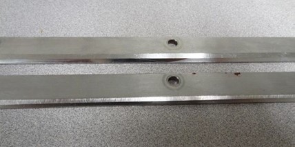
FIGURE 1. Clamps that have been rubbing and damaging anilox engraving

How does a printer make the most out of his or her enclosed chamber application? Chamber success begins by establishing the four processes of documented procedures, proper training and evaluation, component maintenance and establishment of workspace.

  • Documented procedures include how to build a chamber, calibrate it, install it and clean it properly. Seek supplier input and have your team tailor the chamber to your particular design.
  • Proper training and evaluation: Set up a system of mentors, expect employees to be able to demonstrate they can successfully build and clean each chamber.
  • Maintaining components is critical. Worn parts must be replaced. Inspect frequently to keep the chambers sound.
  • Workspace: Designate an area for chamber cleaning and building by establishing a cleaning station supplied with spare parts.

When we speak of getting the seal, it is not just referencing the seals on the ends of the chamber, but also how well the blades seat properly against the anilox. In many respects, the seals and the metal blades form a complex gasket to prevent ink leakage while maintaining a stable, ink-laden anilox surface.

How do we accomplish this seal and make it endure?

Keep Components Clean

As with any device, there are critical areas that must be in pristine condition to maximize desired performance criteria. For the enclosed chamber, the blade rest area is just such a critical point. This is the location where the installed blade should lay completely flat. Any ink debris along this area will prevent the blade from laying flat and will possibly cause a gap through which ink can travel. It also causes waves in the blade and creates uneven metering and wear detrimental to the life of the chamber, the anilox and the consistency of printing. Additionally, blade clamps must be clean, as dried ink will form gaps that liquid ink can pass through and create lengthy cleanups, lost ink and time.

Many chamber designs feature venting to prevent a vacuum from forming. Chamber ventilation is typically used when a chamber has an active pump displacement to drain the chamber, as opposed to a simple gravity drain. Failure to keep the vents free and functional causes the chamber to vacuum itself to the anilox, causing damage to the engraving.

Keep Components in Specification
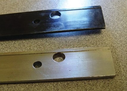
FIGURE 2. Bent and pitted components that will not perform to machine tolerance

FIGURE 2. Bent and pitted components that will not perform to machine tolerance

Now that we have established the importance of well-fit components to the whole package, we must look to how we clean those components. Ideally, any cleaning method should not modify or damage those components in the act of getting them clean. If you use a metal scraper, think of it as machining the surfaces it contacts. Abrasive pads also sand away material and become an unwanted machining process. Employ plastic scrapers or sponges to do the cleaning. In the long run, the chamber builds will be sound and repeatable, and cleanups are minimized because leaking is minimal. Training on how to properly clean them is essential to establish good habits.

Component handling matters. If chambers or clamps are dropped, they can become warped or bent. This takes these items completely out of their machine-tolerance specifications and renders them useless. If parts are lost, such as the bolts that help fasten the components together, make sure they are replaced with the correct threading and length. Windings inside thread holes can be stripped due to the wrong bolt being used. Recognize when the components have reached the end of their working life. If you see pitting, loss of metal and surface tolerance like rounded edges on components, then it is time to replace them. You will spend much more time and money addressing the constant leaking that can result than what it costs to get the proper components you need. Examples of components and related problems are shown in Figures 1-3.

Build the Chamber Correctly

When it is time for assembly, the parts you aren’t cleaning (such as blades and seals) are needed. Always make sure to use the correct blade and seal dimensions. Document this knowledge because, as time passes, mistakes can be made and can create havoc with chamber performance. Maintain instructions on how to assemble the chambers. Write these details to meet your particular needs and design requirements. Always supply training on assembly and inspection, and have the builds “signed off” on and inspected for quality.

For chambers requiring bolts, make sure that proper torque is applied after the blade and blade clamp are installed. Use a torque wrench to prevent thread-stripping of the chamber from overtightening. Also, start tightening from the center bolt and work your way out to the ends. If you tighten a bolt from one end or both ends, the blade will not be laying flat, but will buckle. There is only one right way to do this – to start from the center bolt and work your way to the ends. Examples of proper and improper builds are shown in Figures 4-5.

Keep Chambers Aligned

Chamber alignment allows the specifications you have worked so hard to maintain during cleaning and assembly to matter when you apply the chamber to the anilox surface. Alignment is directly involved with the support assembly that holds the chamber in press. Past excessive-pressure abuse and wear in the assembly components can lead to misalignment and poor chamber performance. Without the chamber lining up perfectly to the anilox, the seal and blades forming the complex gasket cannot, in turn, line up properly. Alignment – not over- pressurization of the chamber – is the answer to this problem.

Most chamber-support assemblies will go out of alignment at some point, even under the best of circumstances. Testing alignment is simple if you follow this procedure:

  1. Start with a clean chamber and metal blades of correct dimensions installed.
  2. Use metal blades for alignment, even if you don’t normally use them.
  3. Make sure the blades are laying
  4. Do not use seals at this point – they may interfere with the blades laying
  5. Install the chamber as you normally would.
  6. Bring the chamber up to but not where the blades are touching the anilox, and check with a bubble level to ensure – at least in a coarse fashion – that the chamber is square and level
  7. If your bubble is centered, go ahead and bring the chamber in to the anilox itself, just enough to where the blades are lightly touching the anilox surface.
  8. Use a gap gauge – 0020 in. – to check the fit between the blades and anilox. Check top and bottom, both ends and center. If all is well, you should get a “snug” response from the gauge. If something is amiss, you will find uneven responses from the gauge. If all is square, back out on the chamber and install plastic blades if you normally use them, install the seals and then you are ready to go.
Examples of misalignment

One blade is touching the anilox and the other is not, indicating an “overbite” by the chamber; the center portion of the blade lengths are touching the anilox but the end portions are not. This indicates the chamber is warped and vice versa; if the chamber is skewed axially, you might find a tight fit for the gauge in one set of opposite corners while being completely free in the other set.

Checking alignment will firmly identify problems either with a warped chamber or fatigued or damaged support-assembly components. Address these items immediately, or many problems with anilox wear, poor print performance and leaking will arise.

FIGURES 4-5. Proper enclosed chamber build (left) and improper build (right)

Mechanical or Pneumatic Issues

The mechanism of applying the chamber to the anilox must be sound. Does the mechanism pre-load the chamber without any adjustment That might be a sign something is not working properly. Can you activate and deactivate the chamber with the chamber going to the proper position evenly and fully every time If not, you cannot guarantee an even load.

The components of the chamber engagement system can fail as well, so they must be maintained and inspected. For pneumatic systems, confirm that the air supply is clean and at the proper pressure and airflow (in cfm) at all times, or performance will be inconsistent at the minimum. If you use an active displacement pump to remove ink from the chamber, any ventilation on the chamber must be free or the resulting vacuum will cause extreme blade over-impression and possible chamber contact with the anilox surface.

Avoiding Anilox Damage

Chamber systems have advanced requirements to prevent anilox damage. Chamber stops, magnets and filters in the ink system help intercept much of the debris that may find itself passing through the closed-loop ink system.

Failure to address debris accumulation or formation leads to frustration and print defects caused by score lines in the ceramic surface. Anilox scoring is more prevalent when using chambers for a few reasons. One is the fact that any debris that gets into the ink system cannot settle away from the anilox as easily due to the closed system and close contact with the anilox surface. In a two-roll tray system, the particles can settle away from the blade/anilox surface area so the concentration and, therefore, the potential for scoring is much less. The fact that the chamber will have two blades contacting the anilox instead of one increases the risk.

You can control scoring if you have an action plan to keep debris away from the ink system, can maintain light blade pressure and have debris-interrupting mechanisms such as magnets and filters. Certainly, when debris is ignored, these small particles can overwhelm the maintenance systems you put in place. Light blade pressure also applies during an auto-wash or manual cleanup because of the greater risk of ink starvation and damage from debris. Solvent and water do not provide the necessary lubrication, so never leave an engaged chamber system circulating for very long. Once the anilox is clean and rinsed, pull the chamber. Don’t assume preventative measures will be enough unless you have taken these other steps and practices to limit debris generation or contamination.

Conclusion

Enclosed chambers are underappreciated as an integral, core component to every high-speed flexographic or gravure printing process. Despite their everyday use and frequent manipulation, chambers are forgotten precision-fit devices that can either greatly assist or hinder print production. Successful enclosed chamber use begins with documented procedures, proper training, maintaining components and having ample workspace. Success is then sustained by understanding how and why achievement of the seal – with the lightest amount of pressure and maintained calibration – makes all the difference in implementation. A converter can get peak performance from enclosed chambers if they can identify and illustrate the necessary conditions and processes. ■

Sean Teufler, technical graphics advisor with Harper Corp. of America (Charlotte, NC) has 22 years of experience in thefiexographic industry. He is active in the Flexographic Technical Assn. (FTA) as a member of the Supplier’s Council and FQC. He was awarded the 20I2 FTA President’s Award for his work on the FQC UV Spitting Project. Sean has completed Level III FIRST Implementation Specialist certification. He can be reached at 704-557-5I06, email: steufler@harperimage.com, http://www.harperimage.com


Charlotte, North Carolina, October 22, 2012— A leader in surface technology, global roller and cylinder supplier Harper Corporation of America is constantly designing cutting-edge technology and supplies and finding applications for laser engraved ceramics. At the Lion's Den session of the Packaging & Label Gravure Association (PLGA) Global 2012 Technical Conference, Harper Corporation's Tony Donato showcased the innovative ceramic coated laser engraved cylinders to today's top gravure professionals.

A product development engineer, Donato is well aware of the groundbreaking technology that the ceramic coated laser engraved cylinders represent. Held on Wednesday, September 19, the Lion's Den segment of the conference provided speakers with the opportunity to convince three gravure experts that their product is innovative. Donato and other participants were granted 10 minutes each to present their chosen product, after which the floor was opened to a question and answer session.

During the segment, Donato explained the benefits of ceramic cylinders over traditional copper-chrome models while showcasing the popular LaserKote totem pole, which features a high degree of detail and multiple geometries. He also spoke to the merits of Harper's XDI imaged cylinders used for long-running one and two color product gravure jobs and cold-seal applications. Ceramic has a life expectancy that is 10 times greater than the more conventional cylinders. Additionally, the life of the engraving is increased and the ceramic cylinder can undergo reverse metering without damage from the doctor blade. Furthermore, the ceramic material better withstands being inside the press for extended periods of time due to its porosity of less than 0.5 percent.

After completing the presentation and question and answer session, Donato accompanied the conference to Harper's table top, where a QDM with a direct gravure, off-set gravure, and flexo ink proofer were on display to demonstrate their interchangeability with the Phantom QD motorized table.

For more information, please contact Jazmin Kluttz at 704-588-3371, ext. 4292, or jkluttz@harperimage.com

Charlotte, North Carolina, October 6, 2011— Global anilox roll supplier Harper Corporation of America will be participating in the 2011 FTA Fall Conference and Tabletop Exhibition from October 10 to October 12, 2011.

Called “Color in Focus,” this event's tabletop exhibition will provide participants with the ability to meet face to face with some of the industry's most innovative color management professionals.

In addition to having a tabletop at which event goers can meet with the company's color management professionals, Harper Corporation of America will be represented by Sean Teufler, the Technical Graphic Adviser of Harper GraphicSolutions. Teufler will be giving a presentation entitled, “Final Analysis: FQC UV Ink Spitting Project,” on Wednesday, October 12.

Teufler's presentation will discuss the issue of UV ink spitting, which is a phenomenon that has plagued flexographic professionals for generations. A study, assembled by the FQC, has researched and analyzed UV ink spitting and has made some important recommendations pertaining to eliminating this phenomenon. These recommendations will be discussed during Teufler's presentation and are important to all members of the flexographic industry.

Color in Focus will take place on October 10-12, 2011 at the Marriot Union Station in St. Louis, Missouri. Registration is now open and interested individuals are encouraged to register soon, as the event is quickly approaching.

For further information, please contact Jazmin Kluttz at 704-588-3371 or jkluttz@harperimage.com.

Charlotte, North Carolina, August 2, 2011— Global anilox roll supplier Harper Corporation is excited to announce that James Kissner, Harper Corporation’s Senior National Sales Manager, has been appointed as one of three co-chairs for the 2013 Tag & Label Manufacturers Institute (TLMI) Technical Conference.

The TLMI Technical Conference is held bi-annually in Chicago, Illinois. The conference provides industry professionals with a highly regarded event during which they can network within their field, access cutting-edge table top exhibits, and participate in presentations and workshops led by both peers and experts. The information that is shared during TLMI Technical Conferences is important to the growth of the industry as a whole, as it promotes innovation and provides a venue in which industry professionals can discuss new products and techniques.

The 2011 Conference will be held September 6-8, 2011. As an event that attracts large amounts of industry leaders, the Conference requires a great deal of planning, which is why co-chairs are announced two years before their event takes place.

“I appreciate the opportunity to serve the industry,” commented Kissner, “and look forward to this challenge.”

Serving alongside Kissner as 2013 Conference co-chairs are Wade Fouts, from Wilson Manufacturing, and Michelle Shaieb, from Whitlam Label Company.

For further information, please contact Jazmin Kluttz at 704-588-3371 or jkluttz@harperimage.com.