The Anilox Role: Its Evolution & Adaptation to Technological Advancements

First published in FLEXO Magazine, June 2016 issue.

Written by Harper West Coast Technical Solutions Advisor, Trevor Schroeder


The Advancement in flexographic printing continues to progress through scientific testing and proper implementation of new technologies. While each respective flexographic supplier develops, markets and supports advancements within their product, the effect on the overall process is a continued trend toward higher profitability, faster printing speeds, and better product performance properties.

Advances in plate technologies and prepress screening have added to increased ink transfer, and allow for thinner ink films and larger color gamuts. Advances in ink technologies allow for faster press speeds, stronger compositions, and enhanced end use product performance. Expanded gamut, low mitigation, LED UV curable inks, and increased plate transfer all amount to better gross margin control for the converter and more considerations for their successful implementations.

At the heart of the overall process is the anilox roll, faithfully delivering ink in concert with the ever increasing selection of doctor blades and chambers that are developed to increase press speeds.

Developments since the bygone days of rubber stamp printing are remarkable, considering the relative simplicity of the flexographic process. With so few moving parts, flexography is, in a simple word, elegant. However, much like the game golf, the simplicity seems to end there. As Arnold Palmer once stated, “Golf is deceptively simple and endlessly complicated.” Developments in any particular component impact the whole –  a trend which continues to this day.

Anilox technology has always relied on small ink carrying pockets of various size and linescreen for delivery to the printing plate. Initially, these were mechanically knurled cells in copper which were subsequently chrome plated for hardness. Today, the use of chromium (III) oxide (Cr203) applied via plasma thermal spray creates a metallic, glass like ceramic structure which is able to be engraved with a laser to produce these ink carrying cells. The combination of the rapidly pulsed laser and the ability to reshape chromium oxide multiple times with laser energy is what has allowed the familiar hexagonal surface matrix we know today.

FRICKEN’ LASERS

Engraving technology has advanced in step with newer lasers, faster computers and improved software. Carbon dioxide flowing gas lasers were the original choice for their power and ability to drill into chromium oxide ceramic. The carbon dioxide single pulse laser would form cells in a single, spiral pass. This was aptly named single beam, single pass technology.

The shape of an individual cell and the cells around it is a result of the mathematical placement of laser pulses to create a desired geometric formation. With a single beam, single pass laser, the geometry of the engraving is the result of rotational and traverse speed, laser power, beam spot size and the time length of the pulses. The resulting cell shape was somewhat deep and conical, with linescreens in the range of 120 to 800 cpi.

Engraving hundred of millions of cells is not without computational challenges of its own. Anilox laser engravers use the rotational velocity, pulse length and traverse to deliver a precisely timed pulse to the ceramic coating to engrave the cells. Advances in computing power allow for single beam, multi pass, where a cell can be engraved twice –  a simple idea with complete computational implementation. Delivering a pulse to create 20-u sized cell at high speed is akin to splitting a hair with a bow and arrow, out the window of a car, traveling down the interstate. Teo or more separate pulses to a single cell allow for more refined control over the final cell shape. In addition, a larger amount of ceramic could also be displaced, allowing for low linescreen, high volume coating rolls.

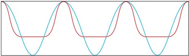
Carbon dioxide (blue) cell profiles engrave a conical, deepcell. Multi beam fiber optic engravings (red) havesteeper walls and flatter cell floors with the same volume. Both qualities promote ink transfer.


The most recent laser technology employed in anilox manufacturing is the fiber optic laser. Fiber lasers are fundamentally different than carbon dioxide and allow for a very high intensity pulse at a very high rate, making it easier to drill an exceptionally small diameter. The reduction in laser diameter allows for extremely high linescreens and yet more refined control over the cell shape. This spot size reduction, coupled with developments in laser beam delivery systems, allow the beam to be split simultaneously.

Thus, we arrive at multi beam, multi pass laser technology. Several laser pulses can be used simultaneously to finesse ceramic into shape; multiple laser passes could be used to displace a larger amount of ceramic while reducing the amount of recast at the top cell craters. These advancements  helped  develop a cell with a less conical volume in favor of a more rectangular floor. Cell walls are thinner and post areas (the area where three cells meet) are better formed. With the flatter floor, there is less depth for a given volume, making a more ef­ficient cell shape; the thinner walls increase ink contact area with plate dots-both properties which contribute to better ink release.

ANILOXES & FIRST

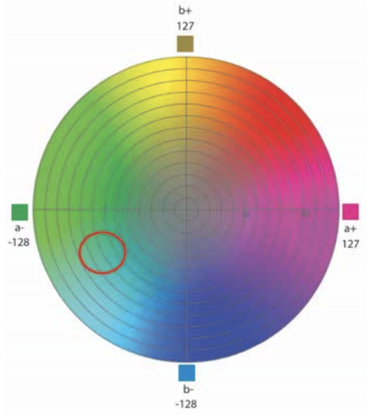
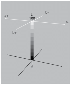
The fundamental purpose of an anilox is to deliver the correct an10unt of ink for a desired film thickness at printable viscosity, while delivering it to the plate with minimal impression. There are several additional considerations including longevity, resistance to damage and important printability aspects, such as a reduced chance of cell plugging and performance at high speeds. Banded roll trials are still the gold standard for identifying job and graphics specific variables. Tonal value increase can be considered while ink targets are hit (or slightly exceeded). In expanded gamut printing, chroma can be maxi­mized before hue shifts away from targeted angles.

“At the heart of the overall process is the anilox roll, faithfully delivering ink in concert with the ever increasing selection of doctor blades and chambers that are developed to increase press speeds.”

As more and more firms adopt expanded gamut and fixed palette col­or, selection and application of technological advancements becomes more critical. Subtle differences with each part of the process can have a large impact on final print quality. Fortunately, the FIRST (Flexog­raphic Image Reproduction Specifications& Tolerances) methodology provides an essential framework for successful implementation of these new technologies.

The initial step in the FIRST methodology is optimizing the printing press. This is a task that should not be looked at as something done in the past; rather, ask the question, “Is the press optimized in its current state, today?” Anilox engraving selection and specifications, substrate, ink, coating, mounting tape and plate materials are all job specific print variables that require optimization. Changes from 4-color process to expanded gamut require re optimization with the new ink systems. Changes from conventional UV to low migration require the same process, as ink pigment selection is limited. Selecting an anilox engraving for these new technologies requires testing, data collection and evaluation.

With the small number of moving parts, a properly metered ink film is critical to success. The anilox roll and doctor blade are a formidable choice for the application, as they are able to meter ink with preci­sion at high speeds. Consistency of the anilox engraving, its surface flatness, longevity and maintenance directly impact the quality of the flexographic process in a production setting.

OUR SAVIOR, THE 60

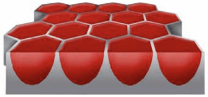
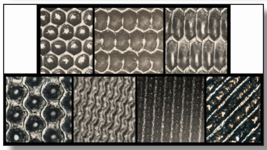
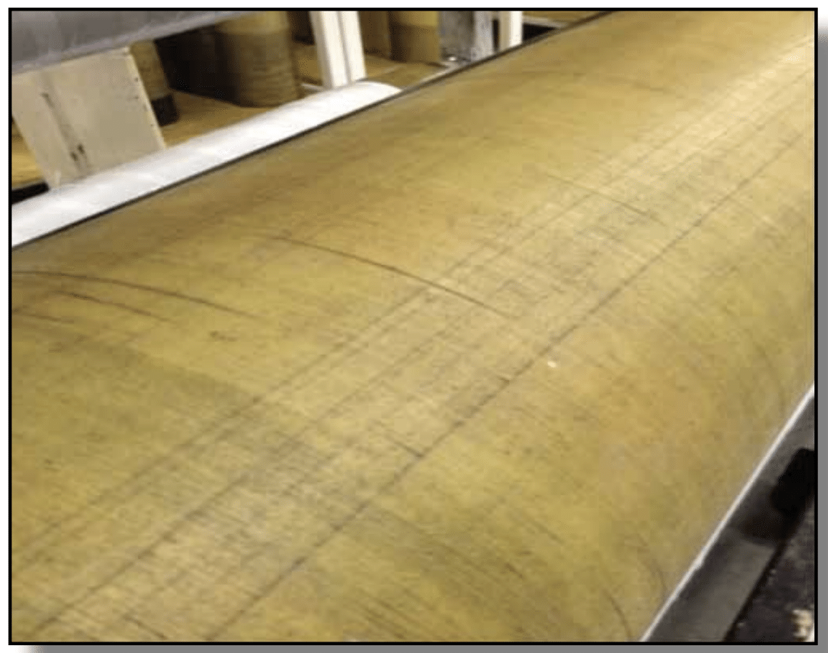
A 60 degree engraving with the familiar honeycomb structure. Cell volume uniformity is responsible for consistent ink film thickness. and walls provide support forfine plate features, such as highlight dots.

It is no coincidence the 60 degree cell has seen such prolific success in the laser engraved anilox industry. The honeycomb conjecture states the honeycomb grid is the most efficient way to divide a surface into equal areas with the least possible perimeter. Although the honeycomb geometry has been discussed since Varro in 36 BC, it wasn’t until 1999 when the conjecture was proven mathe­matically by Thomas C. Hales. Similarly, the densest configu­ration of circles in a two dimensional (2- D) plane is when the center of the circles rest on a hexagonal lattice. This can be seen in a game of pool as the billiard balls are racked.

Laser engraved cells start as a circle; we can think of a lone anilox cell as a crater in the surface of the moon. Energy from the laser causes a microscopic explosion of ceramic; absorbed energy from the laser heats the ceramic and causes it to flow to the surface. This process, called  recasting, is the  foundation to the laser engraving process. By packing these naturally forming “craters” into a hexagonal lattice, we are left with the highest density of equally sized cells on the surface of the anilox. The smallest possible wall area increases the contact between the plate and the ink con­tained in the cells. Sufficient wall area is needed to support highlight dots and prevent over-inking, which can lead to unnecessary tonal value increase.

Flexography has the ability to print a wide variety of specialty inks and coatings on a very diverse range of substrates. This is a key advantage to the competitive edge the flexographic market has seen when compared to other traditionally more expensive print processes. Many specialty applications should be approached as such; testing and evaluating new product offerings allows for the appropriate implementa­tion of technological innovation.

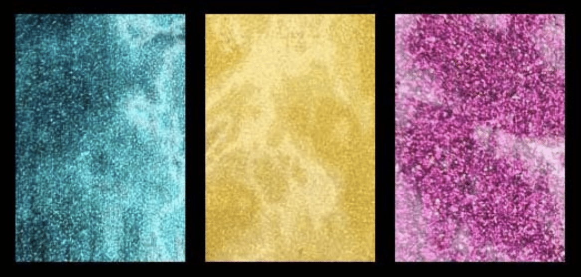
While the hexagon is geometrically efficient, there is not always a need to support fine plate features, such as highlight dots. When appl)1ng adhesive or coatings, or where particles are required to transfer in suspension, fewer walls can be advantageous. This can be accomplished with channels and trenches. By reducing the number of walls, there is more room for particles to flow in and out of cells. Glit­ters, adhesives, encapsulated compounds, functional and electrically conductive inks all require special consideration other than the appeal of a highlight dot. Ink film thickness is one of many critical factors to success in these applications.

Some adhesives, including latex and other water based compounds, require gentle application to prevent foaming or activation. Trihelical and channeled engravings usually provide the qualities needed to outperform in these applications. Encapsulated inks need to make it to the substrate without breaking to allow for functionality at a later time. Electrically conductive inks require special consideration, as conductivity of the printed line is heavily dependent on its application to the substrate. Breaks in the line mean failure for the circuit-an unforgiving consequence in an expensive application.

THE NEW NORMAL

With new laser technology, we see unprecedented control over the engraVIng process. Shaping cells with a laser is a more delicate finesse, rather than a controlled explosion. While the theory remains the same, improvements in laser technology and computational ability have allowed for higher linescreens with improved cell shapes. This level of control allows for the consistency needed for expanded gamut and fixed palette printing.

To harness the most benefit from new flexographic technologies, proper implementation is critical to success. Testing and evaluation is the means to establish the correct foundation to support the rest of the process. When testing, always create a team that includes your anilox, ink, plate, substrate and blade suppliers to make sure you are incorporating the latest flexographic developments. Revisit the fundamentals as part of the project to ensure your current process is optimized
today for a successful tomorrow.■


About the Author: Trevor Schroeder is the West Coast technical graph­ ics advisor for Harper Graphics Solutions, a division of Harper Corpora­tion of America. He holds a Bachelor of Science degree in graphic com­munication from California Polytechnic State University mid a Master of Science in print media from the Rochester

Institute of Technology. His past work has fo­cused on adopting digital printing technolo­gies in conventional printing and converting businesses; he currently provides technical anilox support to flexographic printers and converters in both narrow web and wide web markets on the West Coast. He may be reached attsclzroeder@harperimage.com.


First published in Coating International, 2015 issue.

Written by Harper Product Development Engineer, Tony Donato


There have been a number of articles written on the upcoming revolution of printed functional devices and intelligent packaging. From working with a number of Universities as well as internal testing over the past 5 years I would like to address some of the challenges and possible solutions when trying to print these products roll to roll. I am not going to describe how the print transistors and other multilayer products work but I will state where we are today and what needs to be understood when attempting printing in a roll-to-roll process.

Around 10 years ago, Printed Electronics became the hot topic for futurists, innovators and venture capitalists. There are many examples of successes and failures but, as with motor racing, the old saying «the best way to end up with a small fortune is to start off with a large fortune» has been truthful in both fields. All of the money spent has not necessarily made the investors more money. But, it has helped to move the industry toward the dreams of the futurist.

Printing Electronics

Defining printed electronics has almost become an industry in itself. I will use a definition of «conductor traces, semi-conductors, insulators and or compounds applied in single or multiple layers applied to a substrate flexible or rigid that react or are stimulated with electrical current, gases, chemicals or temperature.» With that said, we need to look at the early days of electronics when the circuit boards were chemically etched and not start off by looking at nanometre dimensioned components of today that are made in cleanrooms in a very efficient method and which have proven to be extremely reliable.

Print Applications

Over the past 20 years, circuits and simple devices have moved into the flat screen-printing process. This process has been used and will continue to be very successful for designs where the trace line widths and thicknesses provide an economic way to produce reliable printed components and devices. All current trends indicate that flat screen-printing will continue to fill the need for my definition. But, as inks and applied materials keep improving to the point that they can provide the same functional performance with a narrower and thinner deposit, roll-to-roll processes like Flexography and Rotogravure are being seen as the processes that can be used to produce products in an economical manner.

When it comes to ink film thickness produced from the various processes used in graphic printing, digital printing typically yields the thinnest film followed, in order, by offset lithography, flexography, gravure, and screen. I believe, as do many, that Flexo and Gravure can be investigated as the replacement for flat screen printing when the demand for products increases and for products being designed where the printed circuits and layers can be combined into what is being call hybrid assemblies. A traditional nano dimensioned switching device (chip) can be assembled into printed portion to complete the device.

Printers need to think about the basics of functional printing. In graphic printing, Flexo & Gravure can place colored dots in a way to trick the human brain into thinking the eye is seeing continuous images as seen in nature. This type of printing can be done very fast, anywhere from 500 to 2000 fpm (150 to 600 mpm). In printing functional devices, we have to first understand that printed inks have to perform under the laws of electrical physics so currents can flow. Overly simplified, «electrons cannot jump» (at the required low voltages) from dot to dot. So, an incomplete printed trace line of ink will not be acceptable.

In moving from flat screen-printing to a R2R (roll-to-roll) process, R2R can be accomplished at very fast speeds. The issue with press speeds today is that we can print graphics extremely fast (500 fpm (150 mpm) narrow web and 2000 fpm (600 mpm) wide web.) But, that also means scrap can be printed extremely fast. For all practical purposes, with exceptions like glucose strips, the number of needed electronics related printed products required for a given batch size, can be accomplished at press speeds in the 50 to 150 fpm (15 to 46 mpm) range to help control print consistency and quality. Currently there is no need for speed at 500 fpm (150 mpm). The functional printed components need to meet a reliability and reject standard far beyond what is required for packaging. Again, we are dealing with electrical physics and not just tricking the human brain with information. That means one of the important issues is how to measure and inspect the printed products. This is one of the many challenges we face in the PE industry.

Ink Selection

The cost of the inks involved can be very expensive and in many cases hazardous. So the obstacles start with the amount of ink needed to start the process. A 5-gallon (20 litre) sump with nano silvers inks costing as much as $1,000/litre is out of the question. The innovative experimenters have been creating micro chambers to hold just enough ink to wet the anilox roll or gravure cylinder. In handling these inks, we also have to explore the reality of handling inks that have particles so small they can be absorbed through the skin into the human body. So, the inks create the challenge of controlling the ink usage and the handling of additional hazardous waste from all clean-up steps.Since more inks are moving to water based, we can look at the electroplating industry where, for years, they have had to develop metal recovery systems to pull all the precious metals from the liquid waste streams. Maybe laundry equipment needs to be made to pull the metals from towels. From the beginning, ink application and handling, waste clean-up, and recovery of materials from rejected printed batches need to be considered.

The ink developers are challenged to find materials that will give the electro and chemical properties and keep the costs down. This is not the only challenge for the ink companies. They also need an ink that allows enough levelling to complete the circuits while, at the same time, keeping the deposit thickness where the ink functional properties are acceptable without allowing the ink deposit to spread. The ink deposits need to stay in place during drying since, in most cases, the gaps and intentional spacing may be very close.

Drying or sintering the inks is a science in itself. Again, ink products must be designed such that, when the carrier is evaporated, the deposited materials can properly function. Many materials need curing at 160°C for 2 to 3 minutes. This may require a sheeting process with the printed products cycled through an oven. There are very creative curing devices that use near infrared in line dryers (curers) and others that have pulsing light sources that are intense enough to sinter (fuse together) the inks into a basically continuous printed wire. The challenge is to match the potential project with the ink and substrate for the equipment you have or want to add.

Substrate Selection

Substrate selection for a given conductive project is very important. Surface flatness and absorption is very critical in order to print a continuous trace line that will have the consistent electrical property (conductivity or resistivity) per liner inch. Films like PET have been used but calendared and coated papers improve the three-dimensional surface finish so that the ink trace can be printed consistently. Like with all printing, matching the surface energies and surface tensions of the substrates and inks is equally important.

Registration

Registration in most Flexo and Gravure presses are .003 to .004” (75 to 100 microns). Some PE related products can be printed with this registration but designers are stating that there are more products to be printed in an ideal printing press at registration at 5 to 20 microns. There are press manufacturers that are claiming a 20-micron tolerance. With this said, it appears that, for the majority of potential products, a narrow web press around 13” (330 mm) print width will be ideal. With that platform, a hybrid press with Flexo, Gravure and Digital decks would be included in the press. The registration system is one of the major press challenges. Again, as earlier stated, speed in itself can be an advantage as long as the quality is maintained. However, speed can also waste precious materials faster.

Novacentrix technician applying nano silver ink with a pipette to print flexo at the FlexTech 2015 conference

Surface Engravings

Metering and engravings have been challenging in both flexo and gravure. In gravure, the cylinder manufactures have been able to make 5-micron trace lines. However, trying to meter to keep hazing to a minimum without pulling the ink out of the trace lines has been challenging. It is much harder to meter across machine lines that are parallel to the cylinder axis without pulling the ink out with the doctor blade. Designing the circuit so that lines are diagonal to the cylinder axis is critical. In many cases, curved trace lines do better than straight lines. Gravure printers have found doctor blade materials and tips that do not wipe graphic ink clean will work on conductive inks. As stated earlier, applying only the minimal amount of ink is critical in both flexo and gravure. In some cases involving flexo printing, the reverse metering typically used may tend to shear the ink. So, a forward doctoring chamber or open system would be best.

In gravure, closed cell structures that perform spectacularly in graphic printing do not necessarily allow the deposited ink to be continuous. Etched or laser engraved channels and open cell structures are required over mechanical or electro-mechanical engraving in many applications. We have developed a laser engraved XOS (Extreme Open Structure) structure to overcome many of the challenges. Also, it appears a softer gravure impression rubber roll (60 Shore A) helps with the printing line details.

In the last year, Flexo has come on as the easier choice with the introduction of 8,000 DPI-RIP (raster imaging processor) for plate imaging. An illustrator created vector image, when converted digitally, has been a problem in creating straight edges in the trace lines. With the 8000 DPI-RIP, the imaged plate line is straighter and cleaner, allowing the relief lines to be narrower and placed closer together. However, photopolymer plates may not hold up to specialty inks that are toluene based. There are flexo plate alternatives available in laser engraved EPDM rubber. The other challenge with Flexo from the image carrier is controlling line width growth from impression. What we see in graphics as dot gain can become a problem when printing precise conductive trace lines. This can be helped with keeping the relief between .015 to .021” (380 to 530 microns).

Flexo EPDM plate being used on a QD Flat Bed printer.

With the availability of anilox rolls in almost any combinations of engraving specifications, flexo has the advantage over gravure in its ability to dial in the ink film thickness for a particular pattern since the pattern is on the plate and the anilox is just the ink carrier. Anilox volumes for printing nano or flake inks do differ, where nano inks are printing nano or flake inks do differ, where nano inks are printed 1 to 3 BCM ( 1.55 to 4.56 cm3 /m2 ), oxide inks in the 3 to 6 BCM ( 4.56 to 9.3 cm3 /m2 ), and flake inks in silver and carbon or graphene 9 to 26 BCM ( 14 to 40 cm3 /m2 ). These are ranges that we have seen but that may not be suited for all inks and substrates. Volume testing is again easier with flexo over gravure. Flexo has the challenge from inks that have low percentage of solids since it has a second ink split over gravure.

Print Environment

The traditional pressroom environment can be an issue. The more detailed the pattern or the more chemically unstable the printed fluid, the cleaner the room and air needs to be. In many cases, the ambient air may need to be a given temperature and humidity in order to not contaminate the printing. Or, air-born dust, if codeposited, may change the functionality of the printed pattern. In depositing advanced materials and, in some cases, liquid electrolytes, corrosion to the equipment would require the printing equipment to be made of different materials than with traditional graphic inks.

The three-dimensional printed trace line is like a wire and the size of the wire is critical toward its physical conductive or resistive properties. As a simplified example, if the printed lines are to carry the current from a 3v battery to a 2.8v LED the voltage drop is calculated in the circuit design. But, if the conductive material is thinner or narrower than calculated, the resistance will increase. The delivered current decreases, the brightness of the LED changes, and the life of the battery is affected.

Conclusion

I covered a wide range to topics to help with your thinking about the challenges associated with starting to contemplate printing functional sensors, devices or circuits. Some of the best advice I can give is to align yourself with a project team that can support the science and physics side of the project so you can just concentrate on the printing side. What I have seen in many incidents is that the advanced materials and electrical engineering project managers do not understand the basics of Flexo or Gravure printing and, in turn, the printers do not understand the basics of electricity. Remember that electrons do not jump very well and variations in ink film thickness and printed line width changes the electrical properties where it can cause the device to not function. Consult the suppliers and universities who have spent the time and money to learn what is needed to make the printed electronics work. As earlier stated, the designs and the required function will be the determining factor in what printing process is best for a given product design.


About the Author: Starting off in paper machinery manufacturing in 1974, 2015 makes 41 years of Industrial experience from manufacturing management and line supervision, plant and facility engineering, manufacturing engineering, production and safety training, technical customer support, application sales, and product development. The last 25 years has put him in pressrooms as a student and a teacher. He has countless hours working as a trouble-shooter and problem solver in pressrooms relating to anilox rolls and gravure cylinders, doctor blades and chambers, pressroom operation, and technical customer support.


To view the original Coating International article click HERE.

First published in Converting Quarterly, Quarter 4: 2015 issue.

Written by Harper GraphicSolutions West Coast technical graphics advisor, Trevor Schroeder


Introduction

One of the core promises of the developing printed-electronics market is the ability to manufacture flexible-electronics products using traditional roll-to-roll (R2R) printing processes at higher speed, ultimately creating a high-value item at a low per-item cost. Many firms and universities involved in printed electronics research are focused on improving the advanced materials for this type of application. Current research is heavily focused on ink and coating formulations, especially low-cost conductive inks (the Holy Grail of printed electronics) and substrates that are printable and do not distort during the high temperature or energy required to cure the ink.


Background

Initial expectations of printed microchips have been set back several years by a number of practical challenges that warrant further research. Lowering costs of traditional microchip fabrication has spurred printed-electronics researchers to pursue a more pragmatic direction. Conductive pathways and their applications (antennae, basic circuits, sensors, etc.) have emerged with modern capabilities of print manufacturing. Today, there is significant improvement in the quality of conductive inks, resulting in improved printability and better reliability. Advancements in curing and annealing technologies have significantly improved the capabilities of wide scale manufacture. While the direction of printed electronics is still being determined, there will undoubtedly be many creative applications made possible from the rapidly evolving industry.

FIGURE 1. A flexible, touch keyboard sensor with conductive grid printed on film; the fine grid lines are designed to remain as transparent as possible while meeting the electrical requirements of each key sensor.

Printed electronics is best grouped under the umbrella term “functional printing.” This can be roughly defined by printing that serves a purpose other than graphic, visual appeal. To be considered functional printing, an object serves a function based on science (physics and chemistry), which can be one of many forms, including 3D objects printed with electrical circuits, chemical compounds, conductive pathways or pharmaceutical applications. Each printed item serves to assist, aid or otherwise interact with a user or device; for example, RFID antennae aid transmission of information between chip and reader. While currently used for inventory control and keycard access, the future of radio transmission devices may include hybrid devices that merge electronics with flexible pathways (i.e.: wearable electronics). A functional item also may be a sensor that alerts when the threshold of a specific chemical is present, such as fruit ripeness in food packaging. Functionally printed items may be concealed or visible. Conductive touch-sensor layers may be designed to remain transparent, while backing layers may wish to mask and conceal (see Figure 1).


Print-manufacturing capabilities

The construction of conductive pathways has evolved from wires to chemical and now to laser etching over years of improvements. Exploring non-screen printing processes is a more recent method that leverages technological advancement from centuries of graphic print manufacturing. Today’s presses and equipment have tight registration, refined impression control, high speed and unparalleled productivity. By replacing the graphic ink with conductive ink, electronic pathways can be printed at high speeds on a wide variety of substrates. High speed for printed-electronic applications currently ranges from 100 to 300 fpm, representing a 10- to 50-fold increase over traditional manufacturing methods. High speeds for graphic applications have reached up to 2,000 fpm because of improvements in every component in the process. It is not unreasonable to foresee an increase in speed for printed electronics applications in the future.


Conductive-ink technologies

Conductive inks can be manufactured out of metallic components (i.e.: flake silver, nanosilver, copper) or carbon-based (i.e.: graphene) and are very expensive because of the required conductive components when compared to pigment-based inks. One fundamental conductive pathway, a trace line, connects two nodes on a circuit. Usually trace lines are designed as thin as possible to control costs, minimizing the amount of expensive conductive ink required to complete the circuit. The carriers of the conductive particles are primarily water- and solvent-based ink components.

After printing, the water or solvent is evaporated, and the conductive particles and any necessary binding agents are left in direct contact with each other and the substrate. These dried particles typically require curing before they exhibit their conductive or insulating nature. Curing may be completed by means of sintering and/or heat curing to coalesce or fuse particles into an uninterrupted conductive pathway. Substrates must withstand sintering or heat curing without deformation or degradation.


Printing methods

FIGURE 2. Conductive trace lines with node attachment points; trace lines may be printed in any direction but should be tested for differences in printability in both the machine- and cross-directions.

Conductive inks are being printed on substrates using many processes, including gravure, flexography, screen printing, inkjet, offset lithography, slot-die coating and blade coating, among others. Each process has advantages, limitations and requirements – each requiring specific ink/coating rheology for optimum performance. Each printing process has limitations on print features that impact conductivity, with trace line width, ink film thickness and ink film evenness being the most critical (see Figure 2).

For example, screen printing can deposit a very thick film of ink compared to other processes but may not be able to deposit as fine a trace line as flexography. These tradeoffs are common not only between print processes but also within each printing process itself. Fluid dynamics and mechanical attributes of each printing process need to be considered: Trace lines may print better in the machine direction (in line with a web or sheet) when compared to the cross-direction in R2R applications.

Due to the variety of packaging processes and their associated tradeoffs, the following is a quick review of each print process and its capabilities and limitations.

Flexography: Flexography uses a raised-image printing plate created in a relief platemaking process. Plate materials are either photopolymer or rubber and can be easily changed for a variety of artwork or circuit-design applications. The printing plate transfers a film of ink to the substrate after contacting a metered ink film on the anilox roll. The anilox engraving can be changed to vary the ink film thickness. Flexography has two ink splits (plate/anilox and plate/substrate) and delivers a 19-23% deposition. The flexographic process has printed trace lines as thin as 15-30 microns while ink film thicknesses typically range from 0.20-4.0 microns. Ink is fluid at approximately 100-1000 centipoise (cPs).

Gravure: Also known as rotogravure, gravure is a relief process that uses an imaged cylinder with recessed cells to deposit ink onto a substrate. The ink film is controlled by the size and pattern of the engraved cells, which are metered by a doctor blade leaving ink in the recessed print areas while unengraved areas (non-print areas) are wiped clean. Because the metered ink film from the gravure cylinder directly contacts the substrate, it only has one ink split and deposits 40-44% of the ink from the cells to the substrate. Ink film thickness ranges between 0.40-6.0 microns, and minimum engraved trace line width ranges between 5-40 microns, although trace lines narrower than 25 microns present a challenge. Gravure requires fluid ink between 50-750 cPs. Offset gravure adds a transfer blanket roll to the gravure process making it similar to flexography (two ink splits); however, the distinction is that the image is still created with the engraved gravure roll. The transfer roll only exists to transfer the ink from the imaged areas to the substrate. This is useful for rigid, rough, textured and shaped substrates that otherwise would not fully contact a hard gravure cylinder.

Screen printing: Screen printing is the forcing of ink through a mesh screen. The mesh is masked in non-printing areas and does not allow ink to flow through. Screen printing, by its nature, is able to deposit a thick layer of ink ranging from 1-200 microns. Because there is a large amount of ink deposited, trace lines tend to be much larger at 50 microns, while ink viscosities can be much thicker up to 70,000 cPs.

Inkjet: Inkjet uses a small nozzle to eject very fluid ink and deposit small droplets onto a substrate. Particles must be very small to pass through the inkjet nozzle with nano inks being most common. Trace lines and minimum print features are dependent on droplet size, but can range from 3-20 microns while the ink film thickness is determined by droplet size and number of passes. When compared to the aforementioned processes, inkjet is computer-intensive as each droplet is calculated and plotted. The necessary processing horsepower has traditionally limited the speed of the printing process.


Considerations for printed-electronic design

When starting with an idea of an end product, it is important to determine the necessary process best suited for the application. Ink film thickness and minimum print features will directly impact conductivity and other properties required for circuitry (how many pathways can fit in a two-dimensional area). Press speed and production needs must be considered as each process is capable of a certain throughput capacity; R2R processes typically outpacing other methods.

Clearly, there are a variety of methodologies to construct an electronic pathway with a high number of input variables to consider. While most designs start with a vision of an end product, the research required to construct that product is extensive. For companies manufacturing specific sub-components using functional inks and substrates, the testing of all materials is the key to a successful product development process.


Testing methodologies

Four different levels of testing exist, each with their own benefits and barriers: outsourcing, small-scale laboratory testing, medium scale pilot testing and finally, full-scale production testing.

Outsourcing is an option for processes that are easily defined and can be tested with established, controlled parameters. These parameters need to be thoroughly communicated between development engineers and laboratory technicians performing the test. As the printed-electronics market is emerging, outsourcing is a limited option at present.

The testing of all materials is the key to a successful product development process.

Small-scale laboratory testing can be completed with limited capital investment and provides the ability to test inks while determining important parameters that affect printability: viscosity, solids content, drying, rewetting and ink-substrate compatibility. Small-scale testing allows conductivity to be measured and ink performance to be evaluated. Trace line widths and ink film thickness can be tested and adjusted as necessary. Ideally, this laboratory testing can be completed with very little consumption of high-cost inks and substrates.

Medium-scale pilot testing can be completed with custombuilt equipment or selected components from widely available converting equipment. This stage is intended for small print runs that prove the concept for full-scale testing.

FIGURE 3. Proprietary proofing system with flexo-plate cylinder and mounted EPDM plate for conductive-ink testing

Full-scale production testing is a final step in the development cycle and most likely would require a partnership between a laboratory and converter. This final step incorporates the experience and expertise of the converter with the engineering requirements of the developer using the inks and substrates that have been previously validated on smaller scale equipment.


Multi-process system for laboratory testing

One solution offered by this firm is targeted directly at both laboratory-scale and potential production testing. A new proprietary proofing system was originally developed for flexographic and gravure ink mixing and color matching. In 2010, Harper was approached by a university looking to test flexography and gravure on a small laboratory scale for printed electronics research and provide demonstrations of their research at the FlexTech Alliance tradeshow, 2015FLEX. The design of the system was readily expanded to become a multi-process platform.

Today, the proprietary proofing system can replicate flexography flood coating, flexography with imaged plates, direct gravure and offset gravure. The system uses a flatbed printing platform and is capable of depositing inks between 2.75-5.0 in. wide and up to 27 in. in print length. A small amount of ink is placed between the doctor blade and the anilox or gravure cylinder on the appropriate printhead; the printhead then traverses a stationary substrate that can range from thin films to 3/16-in. rigid glass or board. After the drawdown, the printhead is removed without tools for quick and easy cleaning. Using pipette-applied ink reduces the amount of expensive inks since there is no need to fill a pan or chamber. Each drawdown can be evaluated for printed properties, and subsequent trials can be adjusted as necessary.

The proofer table is available in manual, electric or pneumatic power, allowing the researcher to select a model that prints at the required speed. During initial testing, it was found that consistent loading pressure is a crucial parameter. Impression is controlled by a spring-loaded lever arm that holds the printhead against the substrate. Springs are changeable to find the correct loading pressure for the image, ink and substrate.

For flexographic models, printheads are available with repeat sizes of 2.356 in. and 6.67 in. to test a variety of applications. Plateheads are available as in-the-round engraved EPDM rubber or a plate cylinder for mounting photopolymer or EPDM plates in 0.067-in. and 0.045-in. thicknesses (see Figure 3). Anilox rolls are easily changed to alter ink deposition and test a variety of ink film thicknesses.

Ink film thickness of a particular ink is a direct variable in the conductivity of a pathway.

For projects with circuitry design, a photopolymer plate can be changed easily and is durable enough to be mounted and unmounted many times. It has been found that the new proofing system is very useful for testing a variety of plate materials and the latest plate-manufacturing technologies. Flat-top dots, platesurface texturing and dual-durometer plates can be tested to see how they interact with different inks and substrates. Testing imaged patterns or flood coats can be used for ink development to see how inks lay down with different conductive particle sizes and resin systems. Using the modular nature and its flexibility, the proofer can be used for multilayers and even multiple processes by adding registration marks to the imaged materials. With sufficient trap (overlap) between layers, even complex projects can be tested.

FIGURE 4. Proprietary proofer with direct gravure XDI cylinder printing conductive-ink test patterns on film. (Courtesy of Tony Donato, product development engineer, Harper Corp. of America)

Ink film thickness of a particular ink is a direct variable in the conductivity of a pathway. In graphic printing, the ink film thickness directly relates to the visual strength associated with a particular ink film; certain pigments require certain thicknesses of ink to achieve a desired color. Anilox rolls deliver ink to the printing plate and various thicknesses can be achieved by changing the linescreen, volume or geometry of the engraving. The amount of ink delivered can be tested to determine the conductive or resistive nature of the ink. The new proofing system uses this firm’s laser-engraved ceramic cylinders as flexographic anilox rolls or gravure imaged engravings (see Figure 4). Harper has the ability to laser-engrave ceramic cells as fine as 2,000 cpi with 0.5 bcm to 70 cpi with 40.0 bcm for the new proofer (cpi = cells per inch; bcm = billion cubic microns per sq inch of engraved surface area).

Both flexography and gravure printing use engraved cells for ink deposition, and therefore print quality is directly dependent on engraving linescreen, volume, and geometry. The new proofer can use engravings, such as traditional 45º quad, 60º hexagons, elongated hexagons, channels and open-cell structures. The different engraving geometries may affect the performance of the ink, and thus, small, changeable rolls benefit the research process.

Other attributes of printability can be tested through iterations of drawdowns, such as ink drying and curing, which are both important factors in successful printing: 1) If an ink easily rewets due to high resolvability before curing, applying multiple passes may pose a challenge; 2) If an ink does not easily rewet, ink can dry onto the plate, anilox or gravure roll, proving difficult to keep the small cells open. Cleaning methods can be evaluated for effectiveness and resin systems can be adjusted for improved printability. Understanding how an entire process will scale to full production improves development time and saves valuable press time in the future.


Conclusion

For many engineers considering high-output applications, flexography and gravure are promising for their high-speed, R2R applications on a variety of substrates. Establishing a project outline is critical especially when developing printed electronics and other functional projects. Work with material suppliers and equipment suppliers to understand necessary starting materials. Leaning on the expertise of suppliers for technical assistance can save valuable research time and help avoid common pitfalls.

What can be learned from using this firm’s new proprietary proofing system to test conductive inks is up to your imagination. We want you to excel in developing your new product for this exciting, emerging industry.


About the Author: Trevor Schroeder, West Coast technical graphics advisor for Harper GraphicSolutions, a division of Harper Corp. of America (Charlotte, NC), holds a bachelor of science degree in graphic communication from Cal Poly (San Luis Obispo, CA) and a master’s of science in print media from the Rochester Institute of Technology. His past work has focused on adopting new technologies in conventional printing and converting businesses, and he currently supports the HarperScientific QD and the universities and researchers testing conductive materials on the system.


To view the original Converting Quarterly article click HERE.

Examining Options & How to Make The Right Choice

First published in FLEXO Magazine, June 2015 issue.

Written by Harper GraphicSolution Director, Alexander James


Anilox engravings have evolved from a rudimentary ink carrier—originally a 45 degree quad engraving, primarily for solid ink coverage—to a highly sophisticated carrier for a wide variety of applications from varnishes and laminates to specialty inks.

With all the various needs and different application requirements in our industry, thankfully today there is also a wide range of anilox engraving and specifications to choose from. They include:

• XLT 60 degree

• 70 degree hex

• 45 degree quad

• 30 degree channel

• Weave

• KatRon (elongated cell)

• 45 degree trihelical

• 60 degree XTR

• 70 degree XTR

• 89 degree XTR


COATINGS

Laminates, varnishes and adhesives: Each has a different purpose and when determining what anilox specification is needed, it will first be necessary to request the Technical Data Sheet (TDS) from your coating supplier. The TDS will provide useful product specific information, such as the application method, appropriate substrate, recommended coat weight, viscosity or pH, percentage solids, dry rate, storage and handling.

For the anilox supplier, the useful information on the TDS includes the target coat weight, percentage solids and the weights per gallon. Coat weight can be based on lbs./ream, gram/square meter or target thickness in microns. Knowing the application method will also be necessary; is it a gravure coating station or traditional flexo application? Will the application be in a two roll or chambered system? Providing this information will enable your anilox supplier to make the right recommendations.

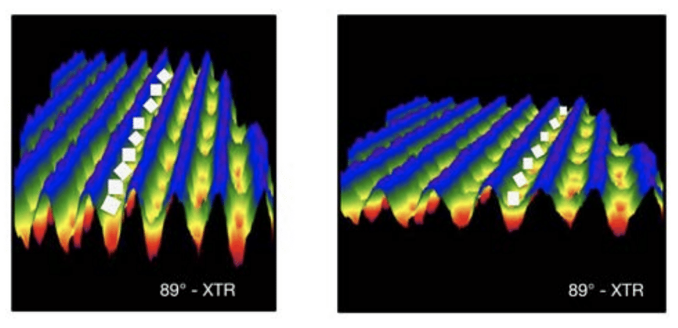
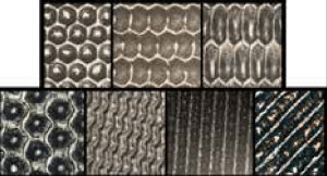
As an example, if the coating is very thick and is going to be applied to an uncoated substrate, then it makes sense to use large cell engravings, such as the 45 degree quad, 70 degree hex, KatRon or one of the channel engravings. Uncoated substrates will necessitate heavier coatings because of the absorbent characteristics of the material. Weave engravings, 30 degree channel, 45 degree trihelical, 60 degree XTR, 70 degree XTR or 89 degree XTR; channel engravings naturally will lay down lots of product due to the continuous open channel patterns. Some very thick coatings will need the channel engravings in order to achieve the recommended coat weight. Coatings require thicker application and, naturally, the larger open engravings are a good fit. With the information provided on the TDS and a Coating Application Worksheet, your anilox supplier will be able to recommend the correct anilox specification for your needs.


SPECIALTY INKS

Specialty inks, such as fluorescent, thermochromatic, metallic and pearlescent, will require different anilox specifications. Some may need volumes ranging from 4.0 bcm to 8.0 bcm and others may need more. For this category of inks, formulation and pigment grind size will be factors that must be considered. Again, the TDS will be most helpful.

Communication between the customer, ink supplier and anilox supplier will be the most important factor. For each specialty ink, it is critical to discuss the expectations, goal and production setup. You can have the desire to print a brilliant, rich fluorescent color, or apply sparkling pearlescent ink; but do you have the right setup to dry the inks at production speeds?

From the anilox recommendation side, the critical criteria will be the particle size. A good rule of thumb is to keep the cell opening a minimum of twice the size of the largest particle size. For example, if you are applying pearlescent inks with 15-µ. to 20-µ. size particles, your anilox should have, at the minimum, an opening of 40-µ.

Once the minimum opening has been determined, you need to look at the anilox volume. When thinking of volume for specialty inks with large pigments, don’t get distracted with volumes that may have very deep engravings. After all, the pigments will need to be easily released from the anilox in order to achieve the desired effect. Anilox engravings that are very deep will invariably have a conical shape that can easily trap some of the large specialty pigments. There will need to be a balance between the anilox opening and the volume (depth). Try to keep the cell depth to opening at a ratio in the range of 23 percent to 33 percent.

To calculate the depth to opening ratio, use the following formula: D/O Ratio = Cell Depth/Cell Opening x 100.

You will need to consult your anilox supplier for the depth and opening information, which is to be provided in microns. Logically, if you have deep engravings when applying large pigment, the anilox roll will have a tendency to plug easily. Sometimes, as in the case of pearlescent inks, keeping the ink in suspension for proper application will be part of the challenge.


WHITE INK

White ink for most printers is the highest percentage of ink consumed. Part of today’s trend is to have high opaque whites, using UV, water and solvent based inks. When making recommendations for white ink, it is always best to have a specific opacity target. Your opacity target will have an impact on the anilox specification.

When needing volumes in the 8.0 bcm to 12.0 bcm range, the logical choices are the 60 degree hex and the 30 degree channel engravings. If you are applying white to an uncoated substrate, then you should consider larger cell engravings such as the 70 degree hex and the KatRon (elongated cells) engravings. As you move on to the high opaque whites, you’ll need more volume; in that situation the various channel engravings are great options: Weave, 45 degree trihelical, 60 degree XTR, 70 degree XTR or 89 degree XTR.

In today’s market, combining the latest solid plate pattern options with your anilox engraving choices can have an impact on your opacity. The solid plate pattern can result in better laydown—mottle free—and also lower the anilox volume needed in order to achieve your desired opacity target. This is exciting, because that can result in significant white ink savings.


SOLID & COMBINATION PRINTING

With solid and combination printing, the XLT 60 degree hex is a great choice to start with. However, when printing on uncoated surfaces, it is an opportune time to take advantage of the variety of engraving options. Rest assured that, depending on your ink system and substrate, there is an engraving that will meet your needs. In every situation, it is key to have a defined print target with tolerances. This will enable your anilox supplier to be able to consistently provide the anilox specification that meets your needs.

Combination printing, solids and vignettes require a balance between hitting your target solid color and also printing a clean vignette. In that situation, there will be a need for your anilox to have enough volume to achieve the solid, and also a high cell per inch specification, so you can also print a clean vignette. XVR 60 degree anilox engravings with higher cell per inch specification and deeper volumes are the best fit. These engravings, along with proper ink formulation, work well for combination printing. If your minimum dot is large—4 percent or higher—then you can consider other options like the 70 degree hex and other channel engravings. This is especially applicable for the paperboard and corrugated market segments.


PROCESS PRINTING

Process printing requires defined print targets (with tolerances). Having specific print target information will always make it easier on your anilox supplier. Along with your print targets (and tolerances), your anilox suppliers will also need to know the type of ink, substrate, plate dot lpi and target minimum dot percentage. With this information, your anilox supplier will be able to make a sound recommendation.

Consistency and repeatability are part of the print requirement for process printing and for anilox suppliers, the option that delivers those needs, as well as best engraving, is the XLT 60 degree hex. The structured qualities of this type of engraving will assure that you will be able to hit your print targets with the most consistent product. It is critical to know what your minimum dot lpi will be and it is important to measure its diameter. Once you know the specification of minimum dot diameter (in microns) you should keep the anilox cell opening equal to or less than that diameter.

Keeping the anilox cell opening equal to or less than the minimum dot diameter will ensure you can achieve the desired quality of clean printing, especially on highlights and vignettes. With those criteria, your anilox will deliver the right amount of ink to your plate and not over ink your minimum dots, avoiding what is sometimes referred as “dirty printing.”

By far the most popular anilox engraving use in our industry is the XLT 60 degree hex. This is due in large part to the fact that the 60 degree hex has the most support structure compared to the other engravings. Regardless of what your print needs are, rest assured there is an anilox engraving that will work for you. Sometimes this may require banded roll testing in order to determine which engraving and specification will work for your situation. This is especially true when testing a new application and product, or a change in your print process.

In most cases, the key things that your anilox supplier will need to know in order to make the correct anilox recommendations are the following:

• Print target (with tolerances)

• Plate lpi

• Minimum dot diameter (in microns)

• Type of ink

• Press type

• Production speed

• Type of substrate

When you need an anilox recommendation for coatings, specialty inks or white inks, it will be important to clearly communicate the TDS information of the products you plan on using, as well as the goal or print target and your measuring method. Measuring methods, unfortunately, are often assumed, and not knowing exactly what method is used can lead everyone involved astray. Anilox specifications of cpi and bcm have numerical values and tolerances that can correlate to your print target and tolerances. Work with your anilox supplier to determine the right engraving choice and specifications that will meet your needs.


About the Author: Alexander James is the director of Harper GraphicSolutions, the technical division of Harper Corporation of America, and has a Masters of Science degree in graphic communications from Clemson University, as well as a Bachelor of Fine Arts degree from the University of North Carolina at Asheville, NC. With more than 20 years experience in the graphic arts industry, Alex has participated in many industry related events as guest speaker/presenter. He is also FIRST Level III Implementation Specialists Certified and has authored numerous technical flexographic related articles.


To view the original FLEXO Magazince article click HERE.

First published in Label & Narrow Web Magazine, March 2015 issue.

Written by Harper Midwest Technical Graphics Advisor, Shawn Oetjen


In today’s packaging market, brand identity is crucial. Color plays a vital part in brand identity and customers are requiring more accurate color reproduction every day. Lab* color space plays an essential role in the entire color process from color managing files to reading Delta E’s. A basic knowledge of the Lab* color space is useful in understanding the final color outcome. Before covering the specifics of Lab* color space, I’d like to discuss some general color principles to provide an overarching understanding of the color space itself.

Two colors that appear the same will have the same Lab* values yet they may not have the same CMYK or RGB recipe. Variables such as lighting conditions and optical brighteners can skew the perceived color results, however, these are beyond the scope of this article. I have significantly simplified some of the factors and terminology for ease of understanding to illustrate the basic principles and phenomenal power of the Lab* color space. Without discussing the complex intricacies involved with it, thereby allowing all readers a basic understanding of Lab*. For those color geeks out there who may be offended by the liberties I am taking, please accept my sincerest apologies.

What is Lab*?

Lab* is an independent color space which makes it a powerful tool. It is the hub for color management color conversions. Lab* assigns numerical values to color allowing us to quantify color data, thus making it unambiguous. So WTH (What The Heck) is an independent color space and why is it so special? To attain a better understating of an independent color space, let’s first talk about its opposite, the dependent color space. CMYK is a great example of a dependent color space. In the simplest terms the color output of a dependent color space is dependent on many variables in the print process. If you printed 25% cyan 50% magenta 0 yellow and 0 black on three different types of presses at three different locations, would the colors look the same? No, they would not because they are dependent on the equipment, along with other variables that go into the process. Look at the three samples on the next page. The colors look different even though the same amounts of CMYK inks were printed. If you measured them with a spectrophotometer they would all have different Lab* values (because they are different colors) even though they were made from the same CMYK make up.

The Lab* color space allows you to quantify the color utilizing an independent color space. This means that the values give you an independent value representing that color. In the simplest terms, if you have the same Lab* values you will have the same color, different lab* values a different color. If you look at the three samples they all have the same Lab* values. However, to compensate for the inherent variation in the printing process (dependent color space), the CMYK values for each printer has been adjusted specifically for that process. The result is the same color appearance on the final press sheet. In short, different CMYK percentages have to be printed depending on the print variable to achieve the same color output.

Using Lab* Data

Lab* data, combined with some pretty sweet math equations and computing power, will allow you to manage the millions of different color combinations in process printing throughout the workflow with the click of a button. It will calculate the percentages of CMYK ink needed for each color based on the print sample profile and should bring the colors closer to the intended results. Without the independent color space, i.e. Lab*, it would be more difficult to accomplish this task.

You can’t look at or measure a random color and decipher the exact percentages of CMYK that were used to create it because the final print results are dependent on the many variables that go into the printing process (e.g., ink, plates, substrate, operator). However, the Lab* data is independent and gives you, for lack of better words, the raw color data.

The Lab* color space is based on the three attributes of color: hue, saturation and lightness. Hue is the color itself and will change as you go around the Lab* diagram. Saturation is how bright or vivid a color is versus how dull or gray a color is. As you move away from the center of the color wheel, the colors increase in saturation. Lightness is how light or dark a color is.

The Lab* data is collected when a spectrophotometer shines a light on the sample and then analyzes the wave lengths of light that are reflected back to the instrument. Filters or a prismatic grid assist in the data collection. The data is then mapped to three numerical values that correspond to an L, a and b axis. The three axes create a three dimensional color space; think of it as a sphere.

a* and b* Axis

The a* and b* axis work together to create a Cartesian plane and define the hue and saturation of a color. The a* axis is defined as the red green axis. Working from the middle of the axis to the “a+” (A plus) or red side, the numerical values for the corresponding colors increase. From the middle of the same axis to the opposite side, the “a-” (A minus) or green side, the numbers decrease and are thus negative. “a-” is green because the opposite of red on the color wheel is green. Note that the foremost point on the “a+” side is not a fire engine red; it is similar to magenta. I would like to mention that with standard printing conventions it is virtually impossible to get a color at the edge of any of these axes. It can be confusing to keep the orientations straight. One way how I remember “a+” is red: When you receive an A+ on your papers, it is marked in red ink.

The b* axis is similar to the a* axis but for blue and yellow. Working from the middle of the axis to the “b+” or yellow side, the numerical values for the corresponding colors get larger. From the middle of the same axis to the opposite side known as the b- or blue side, the numbers decrease becoming negative.

The a* and b* axes are perpendicular to each other and allow you to identify the hue and saturation of the color. Let’s take a “hands on” look with a few examples. For now we are only going to look at the a* and b* coordinates of a color. We will discuss the L value later.

What is the approximate color with an a* value of -80 and b* values of -40? Use the image above to “plot the color”. The color is going to be a bluish green. The beauty of the Lab* or any independent color system is that you can accurately communicate the color you want by utilizing the coordinate values for that specific color. It eliminates color commentary like, “Can you blue that color up?” or “I was imagining a dirtier color.” Comments like those can mean vastly different things to each person and ultimately result in colors that are not close to customer expectations. This is why numerical expression is so important, to get agreement on the given color.

With that said, it does not mean that I will call this color “a*- 80 b*-40.” Instead, this numerical digital color target, similar to a color standard in a digital form, can be easily shared all over the world, resulting in consistent expectations and color matches. Colors that have the same Lab* values should look the same. However, variables like optical brighteners, lighting conditions, and metamerism can lead to different appearances.

Below are a few other colors to plot ensuring you have a good understanding of how the ab*axes work together before we move forward. Take a second to “plot” the colors. Write in the approximate color name next to the Lab* values. The answers can be found at the end of the article. Keep in mind, this is just an exercise to build confidence in your understanding of the ab* axes. An exact color match is not crucial, however if the result should be a red and you put blue, you may want to review the first part of the article.

1. a +127 b 0 Approximate color: ___magenta_____

2. a +100 b +100 Approximate color: ___red_____

3. a +127 b -127 Approximate color: ___purple_____

4. a -80 b +76 Approximate color: ___green_____

In flexographic printing the anilox roll is a crucial part in achieving Lab* values. The volume of the anilox roll is of the utmost importance because it directly effects the amount of ink that is carried to the plate. The anilox cell opening, in relationship to the depth of the engraving, will influence the ink release properties from that specific roll, effecting your ink film thickness (color) of the final print. If you have two anilox rolls with the same volume but different cells per inch engravings, the anilox roll with the lower cells per inch (bigger cell openings) will have an increased ink release characteristic thus resulting in a thicker ink film deposited on the substrate and a more saturated color. The thicker ink film will alter the ab* values. Many inks will hook to the right or left on the ab* axes as you increase the ink film thickness.

L* axis

Now that you understand the ab* axes, let’s discuss the vital importance of the L axis. The L axis is perpendicular to the ab* axes and identifies the brightness or lightness of the color. I have heard both brightness and lightness used interchangeably to describe the axis. The numerical values for the L axis go from 0 to 100, where 0 is “dark” and 100 is “light.” I remember this by thinking about a light bulb; a 100 watt bulb is bright while a 0 watt bulb produces no light and is thus dark.

Let’s take a look at a few examples to get an idea of how this works. A color with the following values, a* = 0 b* = 0 L = 0 is in the center of the axes making it hue-less or gray. The L value of 0 tells us that, in this instance, it is on the dark side of the axis resulting in a dark gray, similar to a black. If we take another color with the following values, a* = 0 b* = 0 L = 50, it will again be a gray but because the L value is at 50 it is a medium gray. If the L value were at 100 it would be a light gray, almost white.

It is a common misconception in flexographic printing that increasing the volume of an anilox roll will merely alter the L* value. This however is not true. Yes, increased anilox roll volume will deliver more ink to the substrate thus creating a “darker” color and a lower L value. It will also influence the color itself because more pigment is delivered thus altering the ab* values as well.

Now that we understand the basic principles of the L a b* axis let’s throw some color into the mix. We have a color with a* = -100, b* = -100, and L = 90 values. Based on the Lab* coordinates, it is a light blue. If we change the L value from 90 to 10 the hue stays the same, it simply appears to be a darker blue.

Test Your Lab* Knowledge

Let’s put it all together and test your knowledge with a short quiz. First answer the questions below. Then match the Lab* values with the correct color block by placing the letter of the corresponding color block in the blank next to the Lab* values. Use the ab* coordinate color wheel from earlier to identify the hue and saturation of the color and then look at the L value to identify the brightness of the color.

  • What is an independent color space?
  • What is a dependent color Space?
  • What color is associated with the A+ side of the axis?
  • What color is associated with the B- side of the axis?
  • What are the numerical values accosted with the L axis and what do they signify?

I hope you have a better understating of Lab* color space and see why it is a powerful tool for not only color management but also color communication. Please remember Lab* was discussed in a simplistic approach in this article to increase understanding. Without Lab* accurately communicating color, it would be next to impossible. How would you communicate that you want a color just a little bluer to someone standing right next to you? Now imagine trying to accomplish that monumental task with someone halfway around the globe – good luck. Lab* is an integral portion along almost every vital crossroads throughout the printing workflow. When you are contemplating an anilox roll change to match a color think about its impact on all aspects of the color. And next time you are in the grocery store, think about the impact that Lab* had on your shopping decisions.

*Answers: 1. Magenta 2. Red 3. Purple 4.Green 1.G 2.D 3.H 4.C 5.F 6.E 7.A 8.B*


About the Author: Shawn Oetjen, Midwest Technical Graphics Advisor for Harper Corporation of America, graduated from Clemson University with a BS in Graphic Communications.Oetjen possess a wealth of knowledge and experience from working in various capacities within the flexographic industry including education, production and sales. He has a keen knowledge and understanding of the flexographic process from concept to execution. Oetjen is active in various industry committees and is FIRST Level II Press operator Certified.


To view the original Label & Narrow Web Magazine article click HERE.

A Guide to Preparing, Proofing & Using Specialty Inks

First published in FLEXO Magazine, June 2014 issue.

Written by Harper GraphicSolution Director, Alexander James


Printers continue to strive for ways to get both the print buyer’s and the consumer’s attention. As a printer, have you been looking for something that makes your printed product stand out among the rest? Are you vying for an edge in obtaining market share in the label business? You should consider the expanding field of flexographic specialty applications. Specialty applications that provide the “pop” in your print cover a wide range of visual stimulations that differentiate a product from the rest.

Some of these include:

• Glitter

• Metallic

• Fluorescent

• Pearlescent

• Holographic

The hard part is getting these inks from plate to substrate. A lot of that has to do with testing, proofing, proper anilox selection and an understanding of the inks themselves.


PICKING “POP”

Before starting on any print project, it is imperative to define the goal. What is the effect you are trying to create? Are you trying to match a print sample or simply wanting to create a dynamic effect? Let’s look at a couple of applications as examples.

Specialty inks are special for a reason. They are unique not only in effects but also in setup, handling and testing. Make sure you understand the requirements to print and plan to run testing before committing product to a customer. We often find that rushing to completion on a specialty ink project has about the same low success rate as a poorly planned fingerprint.

You might start with a popular recent admission to flexography: The realm of tactile coatings. Tactile effects create an interesting interaction between the consumer and the product. Raised bubble areas or dew drops and raised grid patterns on your graphics can create that surprise “wow” factor that helps differentiate your product from the competition by capturing the consumer’s attention as he/she explores the feel of the packaging or label.

You might also consider a specialty effect like a color shift of the graphic image using thermochromatic inks, whose color shift is triggered by temperature change from physical touch or a change in the temperature of the substrate or content of the package. While these are exciting developments for flexo, consider a word to the wise: Before you proceed, be sure to match the ink’s ability with your end print expectations. Accomplish this by obtaining printed examples from your ink supplier that demonstrate printing methods that are at least adaptable to your existing capability.


PREPARING “POP”

So what do we need to do first? Set up a meeting with your ink supplier, anilox supplier and production staff to discuss goals and review how to pre qualify the variables prior to going to production. Request the technical data sheet and MSDS sheets for your specialty ink. These are very informative documents that you and your anilox supplier will need to make decisions. You can expect to find information regarding particle sizes, which can be particularly helpful when dealing with glitter, pearlescent and metallic inks. Often the particle size determines volume requirements because the particles have to be able to fit and sometimes flow within the cells.

These sheets will also indicate an ink’s shelf life, which is often much shorter than standard ink systems. You may be surprised to find a batch life with an expiration date only a month from receiving. Many of these inks have longer lead times because they are not kept on the shelf, but are made to order when needed, due in large part to the short shelf life. Plan your tests accordingly. Don’t order the ink and then push off the testing for months. Make the commitment to test.

Specialty inks may also be somewhat less stable thermally, so the inks must be kept within their temperature window. This means no freezing, no high humidity and storage in a stable window of operating temperature. Make sure you know what you can or cannot add to these inks for reduction and what to use for cleanup. Shocking a batch of ink can be very frustrating in the middle of a trial or during an anilox cleanup. You will also need to verify the type of substrate you are using to make sure the ink you want to use is compatible with the substrate.

Learn what drying requirements are needed. If you are working with an older press running a water based application where you have only successfully dried ink films from 10 bcm volume aniloxes, and you are now going to put in a 30 bcm roll for glitter, you will find out that your drying capacity becomes a great hindrance to run speed and may not dry enough between stations. You are going to want to fully represent your printing process in the trial run. Testing should include the substrate you plan on running in production, the same inks and, where possible, the same setup. This will also give you some indication of potential drying or curing issues you may need to consider when going to production.


ANILOX SELECTION

Once you have decided what your goal is and have the technical information on your ink or coating, it is time to select your anilox. Keep in mind the particle size of your ink grind when dealing with glitter, pearlescent and metallic inks. A good rule of thumb when selecting an anilox is to maintain a minimum anilox opening to particle size ratio of 2:1. This method helps to select an anilox specification with a large opening and shallow depth. With this minimum ratio you will have a greater chance of enabling your ink particles to flow into and out of your anilox, transfer to your photopolymer and result in your desired specialty effect. Guidance from your anilox supplier will help determine which type of engraving will be the best fit.

Thankfully, today there is a wide range of different anilox engravings to choose from:

• 30 degree channel

• 45 degree trihelical channel

• 60 degree hexagonal

• Elongated hex

• 70 degree hexagonal

• 90 degree XTR channel

Regardless of the type of engraving chosen, keep in mind that with this kind of application, you will need to lay down a lot of ink to achieve the desired effect. For example, working with your anilox supplier, if the pigment grind of your ink is 35-40 microns, you will need to select engravings with minimum cell openings of 70-µm. to 80-µm. and 280 cells per inch (cpi) or lower. At 280 cpi, the cell opening is 85- µm. and engravings with lower specifications will have even larger cell openings. There are exceptions to every rule, so you must also inquire about the particle shape.

Some particles require depth, as well as opening because the shape may be more round where most particles are a rod or flat flake and fit in the cells. Round particles need room to fit inside the cell.

Using the engraving specification of 280 cpi with an opening of 80-µm., we can then review how much volume will be required. Consulting your ink supplier, if it happens that you’ll need 7.0 bcm for the specialty ink with flat or rod type particles to work, then review where 280 cpi, 7.0 bcm falls into the chart. You will see 7.0 bcm falls close to the end of the standard (green) engraving range.

Keep in mind the particle “ size of your ink grind when dealing with glitter, pearlescent and metallic inks—A good rule of thumb when selecting an anilox is to maintain a minimum anilox opening to particle size ratio of 2:1.

As the anilox supplier, I would suggest moving to a lower engraving specification, such as a 220 cpi with 7.0 bcm. The reason for making this adjustment is so the engraving is now to the middle of the volume range and the cell opening is a little more than two and one half times the pigment grind. This choice should result in easy ink laydown and less issues with plugging. Note that you can have same volume with different cell counts and cell openings, so consult your ink supplier and anilox supplier. Making the right choice will dramatically impact your chances of success. Make sure you know the condition of the anilox you are going to use. You can easily have the anilox specifications but not get the results due to wear or cell plugging


PROOFING “POP”

It was mentioned earlier that it is always a good idea to conduct as much testing as possible prior to going to press when embarking on new projects. If you are not 100 percent confident in the ink and anilox combination, then consider another step in preparation. This step involves proofing. Proofing is a more cost effective way to determine whether the desired effect is achievable. There is a variety of tabletop testing equipment available that will enable you to conduct proof print trials. You want your proofing device to mimic your press, so proofing that incorporates your ink, anilox and substrate is preferred for repeatability in press. In the case of UV based inks, you can also test curing requirements with small tabletop curing units. Testing will provide a snapshot of potential challenges you may face before going to production if you are considering different run options.

For example, on a tabletop proofing device it is rather easy to conduct a double hit of your ink using different anilox volumes and drying or curing settings. At this stage you can also conduct very cost effective experimentation with a variety of different substrates. In contrast, webbing and running an entire roll of material on press is wasteful, when a few passes on a proofer can achieve the same results. Proofers need to be simple to use. Some tabletop devices have quick anilox switch out options that make it rather easy to change out and test different anilox engravings and specifications. This can be important, especially with considering the need for a double bump of the same material or multiple passes like a primer or opaque white. These various passes will likely use different types of anilox specifications in order to achieve your desired goal. Having it all there for proofing makes good economic sense.

Once you have a good handle on what you want the effect to be, you can then be comfortable making any final tests of design at the press. The “pop” of any specialty ink can be enhanced further by how you include the effect in the design of the product.

If you plan to utilize graphic options and not just print a solid, you may have to balance these requirements with the desired effects. You can use a banded roll that brackets the original volume and line requirements to enhance the printability. Pair a graphic design or designs you want to test with the banded roll and run them at the desired production speeds to test process requirements.


FINAL CHECKS

Other things to keep in mind as you transition from testing to a production setup are ways to maintain the inks, drying and curing options. Make sure you start with an ink that has just been thoroughly blended to get all particles in suspension. All glitter and pearlescent inks must be kept in suspension to create the desired effect and it is reasonable to think some settling will occur, so blend. You may also have to look at ways to keep the inks moving in the pan. Make sure the base system the particles are in is one that actually suspends them. Often we find using a pumping system instead of letting inks sit statically in the tray is better for print consistency.

Depending on your production equipment you may need to do some adjustments with your doctor blade. For example, in single blade setup when applying a thick layer of tactile ink, your goal is to allow the doctor blade to float or butter the coating—not shear it. This will increase the layer of ink that makes it to the polymer and then to the surface. You may need to adjust the web path as well to allow sufficient time for drying or curing. Confirm you have sufficient drying capacity or curing capacity (a minimum 400-w.) or that your curing lamps are well maintained and in good working order. It would be worth having your drying system or UV cure lamps inspected, cleaned and revamped, if necessary.

Think about cleanup, too: What type of chemicals will you need to clean up at the conclusion of your printruns? This will depend on the type of ink or coating used. Each will require a different cleaner and any that are fast drying will require special attention at cleanup time. Keep in mind that regardless which type of ink you use, it is always easier to clean when the ink is still wet. While the ink is being saved for future use, focus on cleaning the anilox before any other component.


About the Author: Alexander James has a Masters of Science in graphic communications from Clemson University and a Bachelors of Fine Arts degree from the University of North Carolina at Asheville, NC. With more than 20 years experience in the graphic arts industry, Alex has participated in many industry related events as guest speaker/presenter. He is the director of Harper GraphicSolutions—the technical Division of Harper Corporation of America—and is also FIRST Level III Implementation Specialist Certified. He has authored numerous technical flexographic related articles.


To view the original FLEXO Magazince article click HERE.

Remembering Katherine Harper’s Charity, Drive & Legacy

First published in FLEXO Magazine, June 2014 issue.


On Saturday, May 3, 2014, Katherine Harper, who with husband Ron built their namesake Harper Corporation of America, passed away. She was 80. The entire flexographic printing, packaging and converting community mourns the loss of Katherine, who was a devout supporter of the industry and numerous charitable and philanthropic endeavors.

Katherine was born on Aug. 23, 1933 in Charlotte, NC to parents James and Margaret Hodges. Her childhood years were spent there, often frequenting her father’s restaurant, Jim’s Grill.

In 1951, she graduated from O’Donoghue Catholic High School. That same year, she met Ron in Wilmington, NC and would go on to raise a family of five children and see grandchildren and great grandchildren through their decades of marriage.

In 1971, Ron and Katherine founded their manufacturing company Harper Corporation of America and installed facilities in Charlotte and DePere, WI. Katherine served as president of Harper’s licensee in Bangkok, Thailand named Harper/Asia Pacific until 2006, when she retired after 36 years at the company’s helm.

Katherine details the company’s early years in her book, The Longer I Live, The More I Learn. She kept her day job at Wachovia Bank while Ron worked out of the back of their home, “selling unengraved printing press rollers to customers he had been dealing with in his former jobs, taking orders and ordering the production of rollers from machine shops.” Her hard work was exemplified in the innovations she pushed forward and masterminded, her ability to solve problems and her steadfast resolve working with others.

Katherine was no stranger to leadership roles in organizations, serving on and leading a number of committees and boards throughout the flexographic world. She served as chair of FTA’s Annual Forum in 1995 in Orlando, FL, becoming the first woman to do so; many of her accomplishments came with the distinction of being the first woman. In 1999, FTA bestowed her with its President’s Award and that same year, the Business Journal honored her as its Business Woman of The Year.

“My thoughts and prayers go out to the Harper family. Katherine was truly “ the most generous person, along with Ron. She will truly be missed by everybody who knew her.”

In 2007, FTA was in the midst of preparing its Technical Education Services Team (TEST) program. Its goal was to author, update and host state of the art curriculums to meet the needs of an ever changing industry. When Katherine and Ron were presented with this aim and a sound business plan, they decided to give a $1 million gift to TEST to help make the program’s vision a reality.

“We believe this will prove to be one of the most important projects ever undertaken by the organization and that it will make a significant positive difference in the success and lives of both current and future flexographers,” the Harpers wrote in FLEXO® ’s October 2007 issue. “We believe that the potential for rapid dissemination of information, as envisioned in the TEST business plan, can make an unbelievable difference in the future global quality and growth of the flexographic process.”

Citing specific tenets of the TEST plan such as its standardized curriculum, accreditation program for instructors and teachers and the FFTA Virtual Print Campus (now named the TEST Virtual Campus), Katherine and Ron shared FTA’s vision of bringing relevant, constantly updated education services to current and potential future flexographers. Seven years later, TEST’s successes can be directly tied to that leap of faith Katherine and Ron took.

TEST is just one of many examples of their desire to inspire future generations to pursue a path in the world of flexography. The Harper name is well known in the industry, not only because of Harper Corporation of America’s role in its evolution but also because of these charitable endeavors. They are many and include:

• Foundation of Flexographic Technical Association’s Ron And Katherine Harper Scholarship

• The Harper Campus, Harper National Flexographic Center and Ron And Katherine Harper Scholarship Fund, at Central Piedmont Community College, Charlotte, NC

• The Katherine Harper Hall, at Appalachian State University, Boone, NC

• The Harper Lab of Flexography, at the Flexo Trade School of Fort Mill, SC

• The Ron And Katherine Harper Flexo Lab at Chicago’s DiTrolio Flexographic Institute

• The Harper Endowment, at California Polytechnic State University, San Luis Obispo, CA

• The Harper Scholarship Fund and Harper Flexo Technology Wing, at Fox Valley Technical College, Appleton, WI

• The Ron And Katherine Harper Scholarship Fund and Harper Center of Graphics Technology, at Dunwoody College of Technology, Minneapolis, MN

• The Katherine Harper Teacher’s Education Fund, from the Phoenix Challenge Foundation

“Katherine left a legacy in the flexographic industry,” said Harper Corporation of America’s Alex James. “Her generosity, along with Ron’s, has touched many lives and through their varied contributions to numerous educational institutions, she will continue to have a positive impact on education of future flexographers.”

FTA President Mark Cisternino, who had the chance to work with Katherine on a number of occasions throughout his career, recalls her overwhelming generosity as “one half of the greatest philanthropic couple in the history of the flexo industry.” He also points to her dynamic, strong willed personality in a time when there weren’t many females in leadership positions.

I am fortunate to have known “ and worked for Katherine. I know she and Ron are looking out over their family with a great sense of love and peace based on a job well done!

“You’d think that this might be intimidating. Quite to the contrary, though—Katherine’s work routinely began when someone (usually a man) told her ‘It can’t be done.’ Her many successes in life were a direct result of this inability to sit idly by and let others call the shots,” Cisternino says. “Katherine and Ron were instrumental in establishing so many educational initiatives around the globe. Their significant positive impact on students of all ages cannot be overstated. I have always been honored to know that Mr. and Mrs. Harper chose to funnel their financial resources, time and talent through FTA and, more importantly, that they considered me their friend.”

“We believe that the key to any successful endeavor—and a happy life—is education,” the Harpers said of FTA. “That is why we choose to support education in an industry that has been so good to us and to an association that has been one of the primary resources for our education during the past 54 years.”


To view the original FLEXO Magazine article click HERE.

First published in Converting Quarterly, Quarter 2: 2014 issue.

Written by Harper product development engineer, Tony Donato


Introduction

From the beginning of flexography – originally called aniline printing – its strength was the process’s ability to print on a very wide range of substrates in a web-fed, roll-to-roll (R2R) method. This strength has lead flexography to be the dominate process of choice for cost, quality and versatility in the packaging segment in North A merica, and it is on track to dominate package printing worldwide. What makes flexo different from other processes is the use of a relief-imaged flexible plate that – after being attached to a cylinder – receives ink from contact with a uniformly engraved roller called an anilox roll. The anilox roller originated as a full coverage gravure cylinder that was mechanically engraved into a copper layer and, after engraving, given a top coat of hard chrome plating. This served the process well, as long as it was doing simple text printing. As the users of flexography saw the potential of the process and the packaging industry experienced the impact of the Nutrition Labeling and Education Act of 1990 [1], the elements of the process improved exponentially through the 1990s, led by the use of an anilox roll that was laser engraved into a ceramic surface.

Because an anilox roller can be used with different imaged plates, pressure was put on the engravers to produce a longer lasting engraving surface. Initially, the mechanical engraving moved from copper and hard chrome to other metals – such as mild and stainless steels – and eventually the top layer of chrome was replaced with a thermal-sprayed ceramic top coating (see Figures 1-3). This increased surface life but still was limited in screen count and volume due to what mechanical engraving tools could be produced, and because the top ceramic coating also partially filled the mechanically engraved cells.

Introduced in the late 1980s, a new anilox-roll surface was developed that used a computer-controlled, pulsing laser that blind-hole-drilled a controlled pattern into a thermal-sprayed, Cr²O³ (chromium oxide)-coated surface. The laser-engraved anilox roller was born, and its evolution has continued moving it beyond the 550 screen-count limit of the mechanically engraved pattern to screen counts of 2,000. Today, the laser-engraved, ceramic (LEC) anilox rolls have proven themselves as the most consistent means of regulating the amount of ink film thickness being deposited onto a given substrate – guaranteeing the desired color densities.


LEC rollers apply to direct-gravure coating

With the evolution of the LEC roller, processing equipment and methods improvements have resulted in increasing the density of the ceramic, improving surface finish, providing variations in engraved geometries and – with the latest 500-watt fiber lasers – have given engravers the ability to engrave very low line screens (20 lpi) with consistent wall thicknesses and volumes to the 100-bcm (billion cubic microns) range. These improvements also have allowed the LEC roller to become used more frequently as a direct-gravure cylinder for coating, laminating, long-running patterns in product gravure, such as décor images and texts on tail-end printers that use a fixed repeat.

The advantages of chromium oxide begins with the coating thickness, the Cr²O³ being applied in a controlled-plasma, thermal-spray process that converts a granulated powder into a coating that can be applied as thick as needed, so the entire engraving is in the ceramic. This gives the engraving the advantage of having the same hardness through its entire depth instead of having only 0.0005 to 0.002 in. of hard chrome to protect the mechanically engraved cells. Note: hard chrome has a hardness of 900-1100 Hv but needs a minimum of 0.001-in. thickness to reach the hardness, and the wear resistance drops below 0.001-in. thickness.

Traditional gravure cylinders can be reprocessed into an LEC surface. First, after the old coatings are removed, the steel cylinder is coated with chromium oxide using the plasma, thermalspray method. The chromiumoxide material is a minimum of 0.005 in. thick and is ground to a T.I.R. (Total Indicator Run-out) of 0.0005 to 0.001 in., then is diamondpolished to 4 Ra to make it ready for laser engraving. The advantage of laser-engraved, ceramic cylinders is their longer life – between 10 to 20 times that of a traditional chromed cylinder.


Advantages of LECs for gravure

One of the biggest advantages of LEC is its wear resistance to the metering of steel or ceramic doctor blades and abrasive pigments, such as titanium oxide and for direct-gravure abrasive substrates. The ability to resist abrasion also allows LECcylinders to be used in traditional gravure-forward metering or where the coating station has a fixed repeat metered in the reverse-blade direction. By reverse-metering, the consistency of the coating thickness is controlled only by the cylinder volume and is not affected by the forward blade angle. Reverse metering helps to keep the process under control longer through the use of an enclosed inking chamber with fixed-blade contact angles and removes the need for an open ink bath as in traditional gravure metering. Removing the open ink bath also helps to keep the ink/coating viscosity more controllable.

The enclosed inking chamber first used in wide-web flexography has two doctor blades – metering and containment – and end seals; this allows the ink to be metered into the engravings and, at the same time, pumped to and from an ink tank that can be covered to reduce evaporation (see Figure 4).

The open pan typical of gravure requires operator skill to set and adjust the doctor-blade angles and pressure that all affect the life of the chrome plating (see Figure 5).

LEC cylinders can be used in all the gravure process variations, especially where the run length is measured in shifts and where the coating weight or finish is critical over the long run (see Figure 6A-6C).


LEC engraving variations

Because LEC cylinders get the engraving geometry from the laser-engraver software and not from a mechanical tool or stylus, LEC engraving variations are almost infinite. The software using the rotary encoder of the head stock and linear encoder of the bed can position a focused laser beam to unbelievable precision, so the cylinder surface can be blind-hole-drilled or cut in a manner that allows almost any geometric shape to be created. The controlled pulsing and placement sequence creates the surface geometry, and the power control varies the depth to give the desired volume for a given line screen.

The traditional 45-deg mechanical quadrangle shape is easily replaced with a 60-deg hexagon that will provide 15 percent more cells in a given area than the 45 deg. Packing more cells in a given area reduces the cell walls and helps in a more even distribution of a coating. The engravings (see Figures 7-15) can be closed cells in a 60-, 30-, 45-deg or elongated variation patterns; 70-, 75-deg or open cells looking like straight-lined threads; (trihelicals in almost any angle 45 deg, 89 deg) to weave like engravings that have parallel continuous walls; and variations where opposing walls look like an hour glass. Note: Not all LEC suppliers can produce all the different geometries; some are exclusive. Consult your supplier for their capabilities and the geometry that is best for your application.


Match LEC geometry to coating application

In choosing the best LEC geometry for your coating application, it is necessary to consider the pigment fl ake size and viscosity. Thinner coatings typically require closed-cell geometry, and the cell opening needs to be suffi cient to allow the pigment to tumble in and out without getting lodged in the cell. For thick coatings, open-cell geometry is most helpful to prevent air from becoming trapped in the cell as the emptied cell returns from the nip to coating/inking system. In most closed-cell applications, due to the difference in the LEC cell shape and the difference in the ceramic surface as compared to a mechanically engraved chrome (MEC) roll, the volume of the LEC will need to be higher than a chrome roll. A good starting point is 15 to 20 percent higher, but the best way to convert a MEC to a LEC is to start with a banded roll. An LEC-experienced technical support professional can review your requirements and put together a 4- to 8-band engraving that will have different geometries, as well as screen counts and volumes.

The 3D images in Figure 16 show how line screen and volume can affect the cell shape and, in the right combination, the cell walls and bottom can be shaped to help coating release and engraving cleaning.

Ceramic is very wear-resistant, so longer-life doctor blades can be used; however, the ceramic has very little impact resistance and can be chipped easily. Unlike traditional cylinders that can be somewhat repaired and re-chromed, the ceramic cylinder cannot be repaired if chipped away from the very ends. It only can be stripped and completely reconditioned. End chips can be repaired with a compatible epoxy, and this repair will help prevent the chip from growing; if the chip is in the end-seal area, this type of repair will help the life of the chamber seal. One other advantage with LEC is the availability of multiple, corrosion-resistant, bond coatings that can be applied under the ceramic to give the cylinder added corrosion resistance.

For coating applications, the LEC supplier will require the lbs/ream or coating dry thickness and process type. Ink and substrate characteristics are important as the ink – percent solids, pigment size, carrier type – helps to choose the type of engraving. For fl exo or offset-gravure application methods, 19 to 23 percent deposition effi ciency is required – a transfer roller is needed. Flexo must have a higher BCM volume. Direct gravure will use a 40 to 45 percent deposition effi ciency and less volume for the same deposition as fl exo. If available, a “smoothing bar” or off-speed reverse method removes lines and levels the coating. Wetting characteristics of the substrate also are important. Wet-out ability is needed to choose engraving type – CPI and BCM. For example, a 30- deg channel reduces pinholing on film.


Flood coating, laminations, adhesives

FIGURES 7-15. LEC engraving variations

Continuous laser-engraved cylinders are perfect for fl ood coatings, lamination and adhesives or primer decks where the cylinder is seldom changed and the repeat stays constant. As mentioned, advantages of the ceramic engraved cylinder is it can be metered by either the traditional forward-doctoring, gravure blade system or a reverseangled, single blade or enclosed chambered inking system. The enclosed chamber application for adhesives, varnishes, primers or laminators also will help control the viscosity of the coating or ink. The LEC cylinder will last so much longer and will allow for the application of tool steel or ceramic doctor blades with a radius tip, so the coating unit’s uptime is maximized with the reduction in cylinder and or blade changes. Also, when the LEC cylinder is fitted with an enclosed chamber, coating efficiency increases due to the ability to pump the coating into and from the chamber, which helps control viscosity and also makes it easier to change coatings due to less inking equipment to be cleaned. In addition, by using a chamber the coating can be pumped from a drum where a mixer can be mounted to help keep the coating components in proper suspension.

Ceramic laser-engraved, imaged cylinders have their challenges with keeping haze to an acceptable level. The quality of the ceramic coating is very important to have less than 0.5 percent of porosity for the LEC cylinder to be used in an imaged application. Ceramic’s porosity can carry ink, which when properly polished, is not a bad thing because it can help lubricate the traditional forward-metering doctor blade as the crosshatching on a copper/chrome cylinder does. Post-engraving finishing is very important to keep haze under control and so is the blade contact angle. For LEC-imaged cylinders, the contact angle of the blade needs to be in the same range as publication gravure – 60 to 64 degs. A thin metering tip is very helpful also; it needs to be matched with the right blade coating or material. When using a thin metering blade tip, the cylinder radius needs to be close to a 1/4-in. to reduce the blade tip from work-hardening on the edges as it oscillates on and off the cylinder.

FIGURE 16. 3D images of various cell shapes


Effect of percent solids on required volume

Tables 1-3 show how the percent solids affect the required volume for a direct-gravure coating or laminating application using a LEC cylinder. All data assume a directgravure deposition efficiency of 42 percent, a 3,000 ft2 ream and 9 lbs/ gal. The tables show, in a logical manner, that as the percent solids decrease, the volume inversely increases, and for 100 percent solids energy-cured inks (EB & UV), the achievable coating thicknesses increases. For a 4 lbs/ream coatweight with only 10 percent solids, it takes almost 93 bcm; at 35 percent solids – 26.5 bcm; and at 100 percent solids – only needs 9.3 bcm.

The other issue that goes along with gravure coating is drying capacity. Just because a large volume cylinder is now available does not mean it can be used. Review the amount of drying capacity available and or what is considered the acceptable coating speed required to make the job profitable.


LEC cylinder handling, maintenance

When using LEC cylinders in gravure applications, extra care is needed in cylinder handling. Always keep covers on the engraving and protect the cylinders from being bumped into the press frames or other corners. As previously stated, ceramic has tremendous wear resistance, but little impact resistance. When cleaning the LEC cylinders use an anilox stainless-steel brush; do not use a brass brush on ceramic. Off-line cleaning systems such as soda or media blasting, ultrasonic tanks and auto-cycle systems all can be employed, but it is always best to consult the equipment and LEC suppliers to make sure the appropriate chemicals, accessories and parameters are used.

After cleaning with any water-based cleaning system, always fully dry by rotating the cylinder, applying alcohol or use oil-free, compressed air. Drying prevents water spots, which can form on the ceramic surface in the shape of quarters on the bottom side, if the cylinder is not dry when rotation stops. In most cases, water spots will show up in the print and they are easier to prevent than remove.


Summary

The advantages of using laser-engraved, ceramic cylinders outweigh the disadvantages in applications of flood coatings, laminating and long-running images or patterns of one to three cylinders.


Advantages:

• Very long working life (10 to 20x)

• Can be metered with steel, tool steel or ceramic-coated blades

• Can be reverse-metered, single blade or chamber-inking system

• Wide range of available engraving geometries

• Closed cells or continuous channels are available

• Can be engraved from TIF (AI) files images or patterns

• Limitless combinations of lpi and volumes (BCM)

Disadvantages: 

• Initial cost (2 to 4x)

• Specification correlation (stylus angle/ percent vs. lpi/BCM)

• Limited number of imaged cylinders – two to three for registered jobs

• Ceramic has very limited impact resistance


Final considerations

When using LEC cylinders for the first time, a banded cylinder may be required to match the gravure coating requirements to the laser-engraving, ceramic specifications. Finally, as for any new project, assemble an internal and external team consisting of your LEC cylinder, doctor blade and coating suppliers. This will facilitate a faster transition from traditional, mechanically engraved chrome to laser-engraved ceramic. In the proper application, you will find your coating/ laminating costs will be reduced and product quality will not be compromised and, in some applications, actually will be increased.


About the Author: Tony Donato, product development engineer, Harper Corp. of America (Charlotte, NC), holds degrees from Purdue and Winthrop Universities, has trained in TQM, ISO and environment compliance, and became FIRST-certified as an Implementation Specialist in 2011. He has 40 years of industrial experience in manufacturing and plant management, line supervision, plant and facility engineering, manufacturing engineering, production and safety training, technical customer support, application sales and product development. In 2013, Tony received the “Top Cat” Award from the Graphic Communications Dept. of Clemson University for supporting the program.


To view the original Converting Quarterly article click HERE.

Key factors in selection and maintenance of anilox rollers to improve quality in highend flexo printing

First published in Flexo & Gravure Global Magazine, December 2013 issue.

Written by Gregory Harms


There is a huge demand on flexographic print shops to reproduce high quality photographic images on packaging substrates. Previously, this area was dominated by the gravure and offset processes, but due to technological progress in flexo printing this has certainly changed. Against this background, understanding the relationship of printing dots to anilox cells will help change the flexo printing process from an art to a science. In this article, some of the steps and aspects needed to take into consideration when selecting the correct anilox for high-resolution halftone printing are discussed. In this context, plate material and screen ruling (lpi) are decisive factors in choosing the most suitable type of anilox.


Influencing Factors

Substrate

In flexographic printing, a wide range of substrates ranging from papers (uncoated, coated, kraft paper etc), foils, and films can be used. As all substrates will behave differently in print and have a different absorption rate, ink film thickness will be crucial.

The choice of substrate and customer requirements will determine the selection of the respective ink system. In general, there are three well-established systems: waterbased, solvent-based, and UV curing inks. The advancement of ink dispersions contributes to improved ink density and reduced dot gain

Doctor blade

Doctor blades and chambered doctor blade systems have also improved over the years and play a key role in controlling the thickness of the ink layer. Blades are available in different thicknesses, tip designs, and materials like metal, plastic, and plastic composite. Tips come in different designs like lamella, radius or bevelled and thickness is a key factor. Values of 0.006”–0.010” (0.15–0.25 mm) would work well in high-quality flexo printing.

As a rule of thumb: »The smaller the tip the cleaner the wipe«

As the ink layer should be as thin as possible, absorption is going to be key factor. Depending on the respective substrate, the absorption rate is found to be related to fluid substrate contact angle and fluid properties. For coated paper, the absorption rate depends on the base paper absorption rate, the coating pore size, coating binder level and fluid-coating contact angle. Films and foils do not have any absorption problem but have to be coated or pre-treated to achieve ink adhesion.

Ink systems

Water-based ink systems have transformed from pH sensitive and maintenance dependent formulations to color matching capabilities with little to no maintenance required. UV inks have maintained color strength while viscosities have decreased to near water-based ink level. Flexography is very much about solid ink density and color strength, both depending on the pigments formulated by the ink manufacturers. Solvent-based inks consist of three main components: carrier fluid, pigment, and resin. Technically, solvent-based inks refer only to the oil-based carrier.

Printing plates

There are a large number of plate types available to choose from to give the one that best fits your process. To determine which is needed to achieve e.g. 150 lpi (59 l/cm) or 200 lpi (79 l/cm), testing a couple with a one color finger print trial, or four color finger print trial might help. The minimum printed dot size is determined not only by the printing process but also by the platemaking process.

A line screen is the measure of how many halftone dots are printed in a linear inch (lpi). Currently, 150 lpi (59 l/cm) halftone screens are commonplace, whereas highend flexo print shops in certain markets like beverages, body care, and pharmaceuticals are printing with 200 lpi (79 l/cm) halftones or even above.

Mounting tape

In addition, plate mounting tape is specially designed for providing high-quality halftone printing and superior versatility for flexo. They are available in the medium to soft range according to the requirements of printing plates and subjects.


Key factors

The key factor in delivering the desired ink film thickness is the anilox roller. To control this tool, the units lpi (l/cm) and bcm (billion cubic microns) resp. cm3 /m2 are used. Lines per inch (cm) means the number of lines (cells) in one linear inch (cm) measured in the angle of the geometry. Volume is measured in billion cubic microns measured in a square inch (cubic cm per sqm). Another key factor is the cell opening, which should not be much larger than the minimum printed dot size on the plate.

This is due to the fact, that if the opening on the anilox is too big, the dot may over-ink, causing dirty print and dot bridging. On the other hand, if the opening is too small, the dot is only contacting cell walls and therefore not getting enough ink to transfer the desired ink layer thickness.

When printing with halftone screens of 150 lpi (59 l/cm) and above, the minimum printed dot size will be 1–2%. In this case, 1% is roughly a 19 micron and 2% is roughly a 27 micron dot size. This means, that anilox rollers with 900 lpi (and above) have a working opening of 25 micron falling between the two percentages. Going even higher, the 1200 lpi anilox has a 19 micron opening which may solve some printing problems.


Test runs

However, before choosing the lpi and volumes, running some print tests using a banded roll is the best way to make the right choice of anilox rollers. Complete a thorough series of trials with the above elements to ensure noticeable differences are observed.

In flexo printing there are a lot of factors which can change the results of the process. This includes the ink systems, whether it’s water-based, solvent-based or UV curing. For example, for the banded roll, testing at 900 lpi and 1200 lpi is recommended, because typically it is good to test the lowest line screen and then the highest with a range of volumes in between to help to achieve the desired print results. For determining the right volumes the density specifications from the FTA – 1.1 Yellow, 1.25 Magenta, 1.35 Cyan and 1.55 or higher on the Black should be used. Usually Yellow and Black are typically the weakest colours, higher volumes are needed in contrast to the stronger Magenta and Cyan hues. For water-based inks, a good range and starting point would be 1.4–2.0 bcm (2.17–3.1 cm3 /m2 ), solvent-based 1.6–2.5 bcm (2.48–3.875 cm3 /m2 ), and UV 1.0–2.0 bcm (1.55–3.1 cm3 / m2 ). The numbers of bands are determined according to the size of the press. For example, five bands like 1200 lpi/1.0 bcm; 1200 lpi/1.2 bcm; 1200 lpi/1.4 bcm; 900 lpi/1.6 bcm; and 900 lpi/2.0 bcm will give a good range of density.

Plugged cells: White light picture (left) and a 3D image.


Cleaning the anilox

Cleaning the anilox is a crucial part of the process. This helps to maintain the ink volume and cuts press downtime through reducing the efforts for colour matching.

Ink volume can be affected by plugging and wear. Of the two there is only control over plugging. In this respect, having a good cleaning procedure and documentation on press is a very helpful tool. Whether water-based, solvent-based or UV curing inks are used, there is always the need to have a good cleaner. It not only should be able to break down the ink, but will also stay wet while cleaning. It is not recommended to use something that will flash fast and dry like water or solvents. After cleaning the roll on press the roller has to be wiped down with a solution that is equal parts water and alcohol. This will get the cleaner out of the cells and off the face of the roll to ensure good ink release next time.

In addition to manual cleaning, a good off-line cleaning machine is also helpful and there are several good products to choose from. Recommendation: Always run to the manufacture specifications, also understand how the machine works, and know the products in use.

However, the biggest step in keeping the aniloxes in good shape is to inspect them before and after cleaning using a scope or a camera system. It is a great practice to know what the roll looks like before and after cleaning. In this context it should be documented when and who did the cleaning of the roll so its progress can be tracked. Moreover, this documentation can help to determine a lot about the roll and how well it is being taken care of. If a camera system for roll measurement is available on-site, the anilox supplier should perform a roll audit at least once a year to determine the volume of the rolls. This is crucial in terms of maintaining the densities on press and decreasing downtime.

The awareness relating to the condition of the rolls should range from wear to cell wall damage. Taking this seriously will contribute to increasing machinery uptime, keeping the rejection rate low, and improving product quality.


Summary

Picking the correct anilox means more than just going to a chart or using a supplier’s recommendations. Although these are great tools, to get consistent results day in and day out requires running banded roll trials taking into consideration all of the elements mention above. Collecting all the data from the trials will help in determining the correct lpi and volume, needed to print highend flexo products. Having the proper anilox is of central importance in transferring the required ink layer thickness and well documented cleaning procedures will help to maintain the cell volume in a controlled manner. These are the key factors in selecting anilox rollers and maintaining quality print.


To view the original Converting Quarterly article click HERE.

Cheaper, More Versatile, Lighter Than Steel Cylinders

First published in Flexo & Gravure Global Magazine, December 2013 issue.

Written by Harper GraphicSolutions Midwest/West Coast Technical Graphics Advisor, Sinesio Garduno


Setup, makeready, changeover—whatever you call it, everyone knows that highly scrutinized periods when the press is not producing a sellable product. Hours, minutes, even seconds spent on setting up the press for its next job is wasted time. How does a printer improve on this? In short: Sleeves. Since their invention, setup times have decreased drastically—from hours to minutes.


SLEEVE BENEFITS

Sleeves have revolutionized press changeovers. They are lightweight and very easy to maneuver, with little effort needed. In addition, sleeves have become so price competitive that the printer can now leave a job mounted for future printruns. This means saving money on mounting tape and needing less labor. This was impossible with steel cylinders, because of printing plates’ susceptibility to being crushed. The price and size of steel cylinders also would lead printers to buy only what was necessary.

Converters had to have extra mounter proofers and platemounter personnel on hand because jobs had to be stripped and remounted every time. Moving a steel cylinder in and out of a platemounter proofer required either a second person or a hoist system. Along with being a potential safety issue, this was a big problem because some pressrooms were run with minimum personnel.

Today’s sleeves are back savers and time savers for most operations. Not many operators in the printing industry were able to lift a solid steel cylinder without developing spinal issues or needing a hoist system. By comparison, moving a sleeve in and out of a mounter is easily done—safely—by a single person. Just like a press station, mounters have a stationary mandrel on which one person can easily load sleeves.

In the past with older printing presses, buying steel cylinders for every size repeat print job was the only option. Most printers, due to storage and cost concerns, would opt not to buy any spare cylinders of the same size. The person doing the scheduling had to take this into account, because of the potential downtime incurred while waiting for a job to be mounted.


When a sleeve is stored, whether a plate is still mounted or not, it is best to stand it on its end (vertically). Storing it horizontally, suspended by a pipe from the inside can cause the sleeve to lose its round shape.

While today’s sleeves are still a sizable investment, they are cheaper than a steel base, especially if a printer can utilize a thin-walled printing sleeve. This means a converter can afford a larger inventory of sleeves. No longer are presses left idling, waiting on same-size cylinders for the next job to be mounted.


EARLY PROBLEMS & SOLUTIONS

Much like smartphones have done to communication today, the newest printing sleeves have revolutionized the flexo industry. And much like cellphones of yesterday, when they were first introduced, printing sleeve technology had a lot of refining to do.

When sleeves first started making their footprint in flexographic printing, I remember lots of trial and error. First, we did not have a gearless press and were sleeving steel cylinders outside of the press and then transferring them to press stations. Old steel cylinders were cut back for the thicker .105-in.-thick plate and with thinner plates we had to use build up to continue their use. Even though cumbersome, sleeving steel cylinders was a necessity due to plate technology and the fact that a lot of converters were switching from 0.105-in. thick plates to 0.065-in. plates.

We had many different thicknesses of sleeves and also had bridge sleeves (repeat builders), which cut our floor space for storing steel cylinders. Print sleeves could be stored tighter together and didn’t require big heavy metal steel racks and hoists.

Nevertheless, we still got a good workout sleeving cylinders and prepping them for the press. One of the biggest mistakes was to push a sleeve beyond the air holes on a steel cylinder or bridge sleeve that had no stops on the end. When this occurred, we had to use our ingenuity to try and get them off without causing any damage to the sleeve.


CUTTING SLEEVES

Another initial obstacle to proper sleeve use, which we still see today, is a lack of proper training. One example is the use of a razor blade to trim back mounting tape. Cutting sleeves with razor blades will cause print defects and weaken their rigidity and stability. Using a Stanley knife or razor blade on a sleeve is not recommended, but in the real world sometimes there is no other option. In this case, it all comes down to training how and what to use to trim mounting tape or plate edges

If possible, look at a sleeve supplier that offers a mounting tape cutline on sleeves. Sleeves cannot be sanded down for razor blade cuts like a steel cylinder can. This will end up changing the Total Indicated Runout (TIR) and diameter tolerances. Using a pre-made cut line on a print sleeve will help make sleeve inventory last longer and maintain print quality.


KEEPING CLEAN

Residue or ink buildup on sleeve ends is another common issue. Inks and solvents can migrate through a sleeve’s composition and start to weaken the edges. A dirty sleeve will be a lot more difficult to put on and take off a mandrel. Of course, this increases setup time and that’s exactly why it’s imperative that any debris gets cleaned off.

Deep cut lines throughout the entire face of a plate sleeve will affect print quality and render the sleeve useless.

Sleeves are very easy to clean. Implement cleaning procedures and you will see a long life and performance from sleeves. This includes any tooling the sleeve comes in contact with—the mandrel and splash guards, for example. Press deck mandrels need to be cleaned and properly maintained to consistently accept the mounting of the sleeve; periodical checks of the mandrels should be done to ensure this. Make sure air holes get cleaned and PSI is set to the OEM’s recommended settings.

build up on them and when this happens, both the plate and anilox sleeve can be damaged. Ensure any other guards near or next to a sleeve never come in contact with it, as this can cause irreparable damage. When it comes to cleaning a sleeve through a machine, it is imperative that the ends of sleeves get sealed off to avoid any cleaner migrating through a layer. This is especially critical when it comes to anilox sleeves—these have an aluminum cladding and most cleaning chemicals are caustic to aluminum.


STORAGE, SPACE & SETUP

When a sleeve is going to be put away for storage, whether a plate is still mounted or not, it is recommended that it is stored standing on its end (vertically). When it is stored horizontally, suspended by a pipe from the inside, the positioning can eventually cause the sleeve to lose its round shape. This is especially critical for an anilox sleeve, due to the inner expansion layer that can be flattened over time.

When unloading a sleeve from a horizontal position, it is also very common for the sleeve to drop and collide with those stored below it. These collisions will typically cause dings on a ceramic anilox face and lead to future corrosion or scoring issues.

Because sleeves are so lightweight and easy to maneuver, this is another potential issue in the pressroom. Often sleeves get end damage from being placed down too hard on concrete floors or not having a rubber mat on their storage rack. Sleeves are a lot more susceptible to getting damaged due to their being lightweight and as such, they cannot be treated as steel cylinders. Unlike steel cylinders, sleeves cannot be repaired; only replaced.

One step that I always see is the rocking of sleeves up and down or side-to-side to get them started on a mandrel. If this becomes an issue, check the cleanliness of the sleeve bore and the mandrel. When mounting a sleeve onto a mandrel, line them up and make sure the air is properly set to OEM specification. Push and twist the sleeve to get through and over the mandrel air holes. Rocking the sleeve to get it started will negatively affect proper fit and circularity, both contributing to TIR issues.


CONTINUED EVOLUTION

There have been many improvements in the technology in the structure of today’s sleeves. In the past, one of the biggest issues was the sleeve expanding and contracting at different speeds. There are many different construction offerings of print sleeves today, varied by manufacturer.

Layers of a Harper anilox sleeve structure.

Choosing the proper sleeves depends on the application and what equipment is on hand. If given a choice, explore a print sleeve manufactured with a non-woven, resin-saturated construction. These sleeves are built for maximum performance and stability at any speed. Some bridge sleeves now also come with a replaceable end slot for locking to the mandrel. No longer do you have to replace a whole bridge sleeve after the notch wears and starts affecting register; you only need to flip or replace the worn end ring. This is a great new costsaving feature available on some bridge mandrels today.

With new gearless presses it is a breeze to sleeve up a press with fixed-base mandrels in each print station. Setup times to prepare bridge sleeves, plate sleeves and anilox sleeves have been cut from hours to minutes. Today’s sleeves are capable of holding the tightest register and printing consistent dots without any high or low spots at very fast speeds.

Print sleeves have tuned flexographic printing to a higher level of quality and made pressrooms much more profitable. While sleeves can increase throughput, they are more susceptible to damage in everyday handling. However, with proper care and training they will be the greatest asset you will make to your pressroom.


About the Author: Sinesio Garduno is the Midwest/West Coast technical graphics advisor for Harper GraphicSolutions. He has more than 23 years experience in the flexographic industry and has hands-on experience on all aspects of flexible packaging production from start to finish.


To view the original FLEXO Magazine article click HERE.