Improve Performance Reliability While Reducing Waste

First published in FLEXO Magazine, January 2019 issue.
Written by Harper Technical Solutions team member, Richard Hernandez


When I was first learning how to run a press, one of the biggest things I could remember thinking was, “How am I supposed to know how these different anilox rollers print?” I would watch all the veteran operators switching out anilox rollers, and they knew exactly which one to drop into press for each job. How did they learn it?

They learned from trial and error. For the development of my understanding, it was much the same. As time went on, I figured out how to use the anilox volumes to my advantage and knew that some jobs would take this anilox, and others would run better with that one. It was all part of “learning the trade.” There had to be a better way to know which one to use, and a better understanding of what it took to obtain reliable performance.

I would like to take the opportunity to discuss how to get reliable performance and a basic understanding of the anilox, while giving an in-depth look at how to get your shop’s ink department and presses correlated, anilox rollers identified, and how to keep things organized and maintained to help you reach the full potential of your anilox rollers. In turn, this will help keep your waste down, help to promote color consistency, and keep production time up.


LINESCREEN, VOLUME & GEOMETRY

Linescreen

Understanding linescreen, volume and geometry, and how they work together is the beginning step to consistent, quality printing.

You may have certain artwork or a certain account whose print dynamics always seem to be a problem when running on press. The simplest solution could be that you are running a plate, anilox, and ink combination that is not made up of the optimum materials for that application. Locking down your anilox selection is where to start.

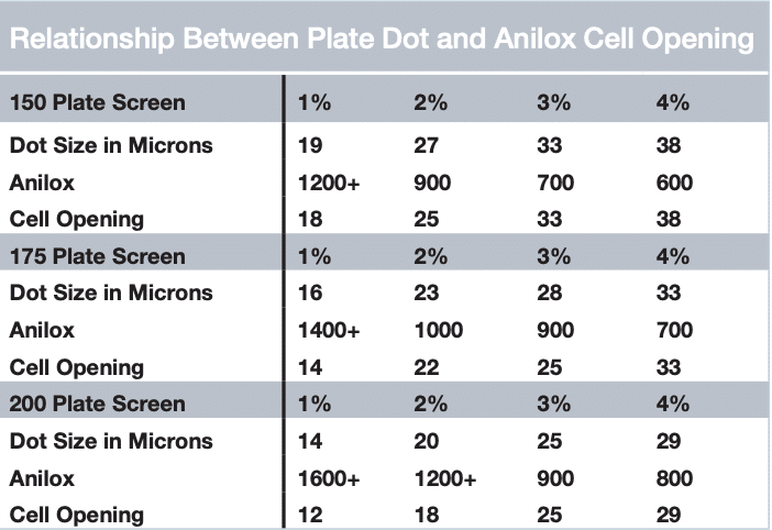
How does line screen play a role in the anilox? The line screen provides the cell opening on the surface of the anilox (see Figure 1). The line screen is defined by how many cells are present per linear inch on the roll (LPI). A properly selected line screen does two things: It allows for distribution of volume without compromising cell quality, and it supports the printed dot. When running artwork like 4-color process, a high line screen is used to help support the low dot percentages, also known as highlight screens.

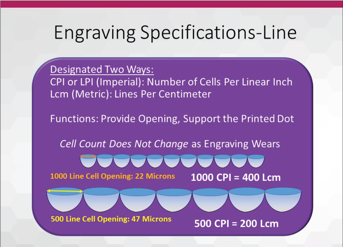
Figure 1: The line screen is defined by how many cells are present per linear inch on the roll (lpi).

Volume

Historically, because the inks are formulated to hit color with thin ink films, your volume will not need to be high. Pairing more open
cells (lowering line count) with a set volume provides a greater deposit efficiency and puts more ink on the plate. The wider opening can be useful in specialty applications like particle transfers. Particle size would then dictate required volume.

Another way the LPI helps is by supporting the printed dot. Knowing the line screen of your artwork and what look you are going to achieve is how you will determine the LPI of your anilox. If you have a high line of artwork, you do not want a low line screen anilox because your dots on the plate will over-ink or under-ink instead of having ink evenly distributed to the plate dots. This will cause the bridging of dots and dirty print since too much ink is distributed. One thing to keep in mind is that the LPI of an anilox does not change with wear. It is always consistent. The only time the line screen will change is when you send it in to be remanufactured and request a different LPI.

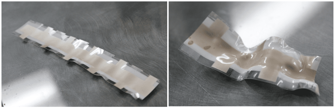
How is volume a factor in anilox selection? Volume is the amount of ink contained in the cells of a defined area (see Figure 2). This is
measured in BCM. A frame of reference will help you scale the concept of the micron: Take one human hair and look at a cross-section and divide from one side to the other into 100 equal width pieces.

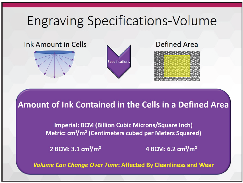
Figure 2: Volume is the amount of ink contained in the cells of a defined area.

Each equal width is one micron. A cell volume of 0.5-2.0 BCM is used along with a high line screen. With a high line screen, not too much ink is needed because you are typically printing fine screens without solids. A volume of 5.0-10.0 BCM is a deep cell, which will hold a lot of ink that will be distributed to the plate. These are typically used for varnishes, coatings, and whites.

You would use these volumes with a 300 LPI to 150 LPI anilox where full solids and complete coverage are needed. In many cases, the volume will be dictated by the ink supplier because formulations are dialed in to specific volume expectations. Always consult with the ink supplier to better understand the needed volumes and why. Volume can change because the BCM will be affected by wear and the cleanliness of cells. As an anilox wears down, the cell will get shallower and not carry as much ink as it did when it was new. Plugged cells immediately lower volume and can only be remedied by a thorough cleaning.

As you can see, the LPI and BCM of an anilox are major factors in how much ink will be distributed to the plate. Both play off each other and cannot work independently. But there is one more factor in your anilox identity—the geometry of your anilox.

We know how the LPI and BCM of an anilox play a role in print. But what is the best way to be assured that the ink is distributed from the cells? The geometry of the anilox is the answer.

Geometry

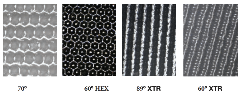
There are so many ink systems in the industry now to help catch the eye of the customer that converters need to be sure they have the tools that can create the expected look. Some coatings are designed to be thin in consistency and others very viscous; there are different geometries that release ink in different ways to accommodate the viscosity. Hexagons, channels, elongated cells, trihelical designs, and 45-degree quads are just a few engravings that are offered to help with converter applications (see Figure 3). Some geometries are universal in application, like the 60-degree hexagonal. Others have niche applications but are more effective. Typically, thin viscosities perform better with enclosed cells and higher viscosities perform better in channel arrangements.

For coatings and inks that have never seen a flexographic press, these often need to be tested with a banded roll to dial in the right engravings. There certainly are exceptions to every rule, so speak with your anilox supplier’s regional technical support about engravings they offer and how they can help.

Figure 3: Hexagons, channels, elongated cells, trihelical designs, and 45-degree quads are just a few engravings that offer help with converter applications.

You will also want to know the needs of your plate material, ink, and artwork, and include their representatives in selecting the correct anilox rollers.


Anilox Audits

The first thing that needs to be asked is, “What is the current state of your anilox inventory?” If you were to walk your shop floor, chances are operators will have their own go-to anilox rollers. They will have a good gauge on their anilox performance, but this understanding must be taken to a higher level to meet pressroom needs. This could potentially be the originator of any color inconsistencies you might be experiencing during a color match. But how do we find out the condition of our anilox rollers? Two words—anilox audit!

Anilox audits are a great tool that will help you identify the three main components we have discussed as well as the anilox condition, so you can understand better what you have and the role each anilox can best play in your production environment.
An audit will also help in identifying which anilox rollers are damaged. A damaged anilox will have many signs, and with the help of your anilox supplier, you can identify the sources of damage and eliminate them. Chipped edges, score lines, worn cell walls, broken cell walls—these are just a few that can be brought to light by an audit. There is nothing more frustrating for printers than to have an otherwise perfectly good engraving get needlessly damaged and render it useless.

  • Chipped edges are usually caused by handling. Bringing an anilox in and out of the press and hitting the press frame is a good example. Another way to get chipped edges is when moving a roller into storage, sliding the sleeve or roll to the back or bottom of a rack, and making forceful contact. A doctor blade unit, sling guard or chamber not properly attached or inserted could also be a culprit. Additionally, corrosion can also loosen the bond between the ceramic and the base and allow the ceramic to flake away
  • Score lines are a tricky defect because they may or may not show in print, and finding the source can be difficult without assistance. Sometimes they are not deep enough to see in the print but are readily identified visually. Sometimes they fall right in the print area and cause an undesired print quality. Identifying the sources of contamination that get in the ink and between the blade and anilox, causing the scoring, is a task with which your anilox supplier can help
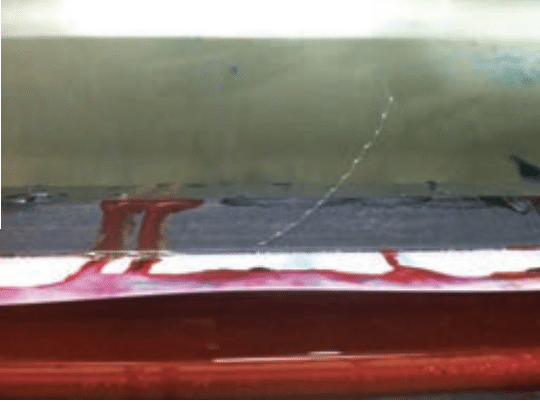
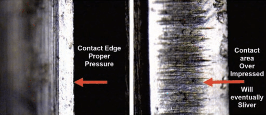
  • Worn cell walls will cause an ink color to print lighter than what came out of the ink department and should be taken out of rotation. Wear can come naturally from use, but you would also have to consider blade pressure, blade holding equipment, and abrasive inks (see Figure 4). One of the most important functions of the anilox audit is to identify worn rolls and get them out of circulation without resorting to press trial and error
  • Broken cell walls will cause the ink to print dark spots. If you have a 700 LPI anilox that has broken cell walls, those cells go from 700 to potentially 500 in those areas, meaning lost dot support and unwanted increases in volume where those spots are located. An operator could be chasing an issue for which he or she will not find an easy solution

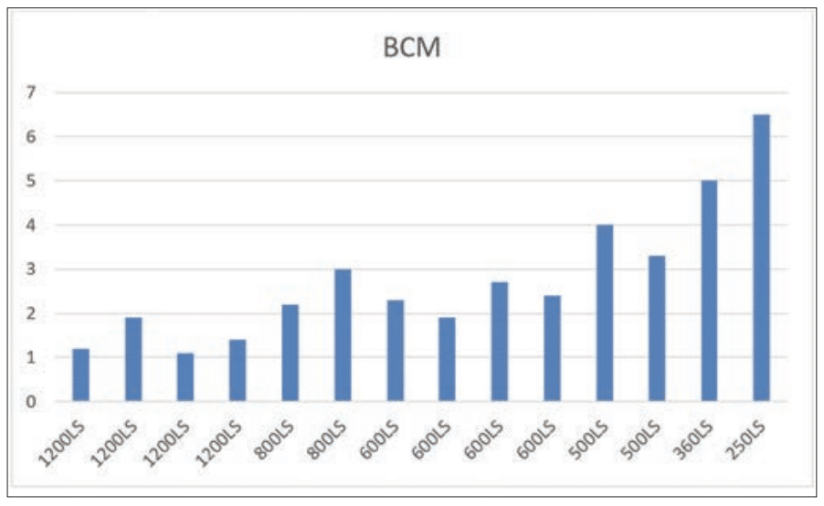
Another way an audit will help is by identifying the line screen and volume of those few anilox rollers that are not marked. We all have seen anilox rollers that are older and have had their identifying marks worn down and made illegible. This will also be helpful in identifying where the proofer roll in your ink department is printing.

Figure 5: After an anilox audit, you will have an echotopography digital volume (EDV) value and 3D image of every anilox to review.

When the audit is graded and returned to you, you will have an EDV value (echotopography digital volume) and a 3D image of every anilox that you can then review and determine which should be cleaned and returned to inventory, monitored in future use, and which ones should be removed and replaced (see Figure 5). EDV is the measured volume of BCM.

If you own anilox rollers that are scored, have chipped edges, or are dinged, you may want to consider replacing those as well. These are factors that can cause print defects. If the doctor blade gets pulled back due to a chipped edge, it may look like a gear mark. A scoreline or ding can cause a void on a full reverse print on an anilox that otherwise matches the color perfectly. Those are just a few problems that could come about from damage that is visible. An anilox audit helps identify both issues that are visible or not visible to the naked eye.

When the anilox base condition is salvageable, you have the option of remanufacturing those engravings as well.

Achieving the full potential of your anilox inventory starts with understanding the linescreen, volume and geometry, then partnering that knowledge with proper inventory management and the useful tools the anilox audit provides. Who would have thought that all this information could have come from an anilox audit?

Knowing the components of an anilox, and how they play a role in your application, will help your workflow move smoothly out your shipping doors.


About the Author: Richard Hernandez is a sales/technical service representative – Western Region for Harper Corporation of America.

He brings more than 24 years of extensive experience in the printing industry with six years in offset printing and 18-plus years in flexography. Within that time, he has gained extensive knowledge of Webtron, Nilpeter, Comco, and Mark Andy Inc presses, as well as A.B. Dick and Heidelberg, offset presses. Richard began his flexographic career at Los Angeles Label, which led to production lead and supervisory experience at The Label Co, and Paradigm Label in California. Prior to arriving at Harper, he was the print manager at Precision Label, which helped him excel in his color matching, team member training and mentoring, and troubleshooting skills. While there, he also assisted with the R&D and product development that helped drive the company into industry-leading trends.


To view the original FLEXO Magazine article click HERE.

First published in Label & Narrow Web, Novemeber/Decemeber 2018 issue.
Written by Harper Technical Service Representative Midwest, Patrick Hogan

Winston Churchill once said, “Those that fail to learn from history are doomed to repeat it.” Fortunately for us in flexography, the industry has learned from mistakes, applied those hard-earned lessons, and continued the dynamic changes that keep our printing technology relevant and vibrant today. While the flexographic printing industry traces its roots back to the 1800s, it has been the constant improvements in technology that have made flexography the vigorous industry it has become over the last 30 years. Developments in press manufacturing, inks, plates, tapes, mounting, graphics, and anilox technology all paved the way for the industry we know today. Of course, the heart of the process has been the anilox. The story of the anilox is an amazing testament to both ingenuity and application.

History of the Anilox

How did anilox rolls come to be? Originally, inks used in the flexographic industry were made from aniline or coal tar derivatives. Early ink delivery systems for flexo were a combination of rubber transfer rolls that had varying amounts of pressure applied to meter the amount of ink transferred to the printing plate. The system was not very precise and didn’t lend itself to repeatability from job to job. As a result, print quality was unpredictable. It was through these struggles the idea for improvement in ink delivery was born.

One of the early flexo pioneers, Doug Tuttle, saw how gravure rolls were being used to deliver a precise amount of ink and looked for a way to integrate that process into flexography. In 1939, he applied for a US patent on an engraved roll used to transfer ink, but because he was interested in improving the flexo process he never pursued the patent so the industry wouldn’t have a single supplier for the roll. The “anilox roll” name came about because one of the early aniline ink manufacturers was Interchemical Corporation, and the suffix used in naming their inks often had an “ox” on it. Thus, aniline inks + “ox” = “anilox roll.”

Initially, cylinders were composed of chemically etched copper. These cylinders were processed similar to gravure cylinders but they had a poor lifespan due to the softness of the metal. Eventually, a mechanically engraved, steel roll was developed as an alternative that could deliver a precise amount of ink. Thus, the anilox roll was substituted in for a rubber roll in the ink train. Using variable pressure between the rolls, varying ink viscosities, and adjusting press speeds revealed the new limits of the early flexographic ink metering method. Early mechanically engraved rolls used inverted pyramid or quadrangular cell shapes. Usually, line screens of 360 cells per inch were not exceeded due to tooling and graphics limitations. In the 1970s, Harper Corporation of America developed the 60-degree hexagonal cell.

The hex has the same pattern as a honeycomb, and as we have learned from nature, it is a very efficient configuration. This cell configuration maximizes the space available to fit in a higher number of cells per inch. The combination of both greater cells per inch and reduced volumes allowed for less ink film thickness; leading to the possibility of advancements in process printing.

Introduction of the Doctor Blade

60° engraving

The introduction of the doctor blade to meter ink on the anilox roll allowed for even more precision in the transfer of ink to the printing plate. Unfortunately, it also led to increased anilox wear. The early steel-covered rolls didn’t hold up to the friction, and moving to chrome-coated rolls helped increase roll life. Chemically-etched copper rolls provided opportunities for linescreen and volume combinations that mechanically-etched rolls could not. A durable coating was needed to protect the copper and it was found that a thin layer of chrome over the copper provided extended resistance to blade wear and improved roll life. To get the chrome to adhere to the copper, the roll was immersed in an electrolyte bath comprising chromic acid, and an electric current was applied to the copper causing the chrome to bond to the copper. Typically, the chrome layer was about .008″ thick. Chrome coated anilox rolls continued to be the industry standard for many years until the ceramic coated anilox was introduced in the 1970s.

While chrome plating was an improvement, even greater resistance to wear was needed. The development of advanced thermal spraying technologies, as well as fine powders, led to the innovation of the ceramic anilox roll. The plasma coating applied to early ceramic rolls was usually an aluminum dioxide – titanium dioxide material. Early ceramic coated rolls had no cell patterns and were just an “as sprayed” coating that didn’t have any geometric pattern engraved. These rolls relied on the porosity of the surface to accept and transfer ink.

Harper Anilox Engraving Technology

In the early 1980s, Harper Corporation of America pioneered the world’s first mechanically-engraved ceramic coated anilox roll to go beyond 200 cells per inch. Converters saw the merits of ceramic coated roll technology with an increase in service life versus chrome coated rolls.

The use of sprayed coatings led the industry to a new terminology – porosity. Porosity, or “void fraction,” refers to the empty spaces in a 60° engraving material. The ability to spray on a coating with low porosity became a critical step toward maintaining consistency while engraving and keeping a uniform volume across the roll face. Today, the top quality anilox suppliers can achieve porosity averages of 1% or less.

Plasma spray coating

In addition, ceramic covered rolls have a much higher “hardness” than chrome covered rolls. This increased hardness makes the ceramic coated roll much more durable and resistant to wear than the chrome covered anilox roll. Typical hardness of a ceramic coated roll averages 1200 Vickers, and is operated in a range between 1,100 to 1,300. Ceramic above 1,300 Vickers hardness will realize changes in mechanical properties and it becomes too brittle. Excessive hardness of the ceramic can cause rolls to crack and fail under pressures associated with regular press operating conditions. New, advanced plasma ceramic coatings made from Chromium Oxide provide a very hard surface within those Vickers specifications while improving corrosion protection. Chromium Oxide polishes well and provides superior resistance to doctor blade wear.

As with any new technology, there is a learning curve. Early ceramic covered rolls had much higher dyne levels than chrome covered rolls and their ink release characteristics were quite different. This would often lead to ink formulation issues when moving jobs from a press using chrome covered rolls to a press using ceramic rolls. Typical chrome covered rolls release ink with a higher effieciency than ceramic covered rolls. A good rule of thumb is to add a minimum 10% to the volume of an engraving when transitioning from chrome to ceramic.

In the late 1970s, advancements in laser engraving technology, along with roll grinding and polishing techniques, saw the advent of the laser engraved ceramic coated anilox. The ability to laser engrave aniloxes opened up new frontiers in flexography, with new combinations of geometries and line screens available. Early laser technology used CO2 lasers to engrave the ceramic. Beam width limitation for CO2 restricted the ability to make rolls not exceeding 1,200 cells per inch. Subsequently, YAG (yttrium aluminum garnet) laser technology was developed. Both of these technologies worked well but because of the cell shape configuration, the depth to opening ratio of cells created by these lasers had limitations with ink release. YAG lasers could make higher line counts, but the cells were even deeper and more cone-shaped than CO2 engraved cells. The industry demanded an improvement in cell count and volume to compete with rival technologies like offset and gravure. Combination printing also created a gap between achievable color and print quality, a gap filled by extended volume aniloxes at high cell counts. Development of advanced digital fiber optic lasers resulted in innovative cell profiles compared to YAG and CO2 technology. Cells less conical in shape and more rounded at the bottom allowed for superior ink release characteristics. These improved cell profiles enabled the digital engraving of aniloxes at even more cells per inch with better control over volume. Line screens of over 2,000 cells per inch are possible. Advanced engravings with elongated cells, channels, and open cells have become available. The improvements in cell quality have kept pace with increasing difficulties in care for and cleaning of aniloxes, and has greatly reduced cell plugging on the press during long runs.

Cell profile progress

The Future of Anilox Technology

The evolution of press manufacturing technology – improvements in dryers, developments of servo drives, sleeve technology, higher press speeds and quick changeovers have triggered changes in anilox manufacturing methods as well. Quicker changeover on presses necessitated the development of anilox sleeves. Wider presses and higher speeds led to the development of carbon fiber sleeves to save weight and provide the stiffness needed to avoid deflection and maintain the total indicated runout needs of modern presses. Typically, anilox manufacturing produces rolls with a total indicated runout of +/- of .001″. The higher press speeds also made it necessary to increase the circumference of anilox rolls to improve ink release characteristics. It boils down to basic physics – larger diameter aniloxes need less force to get the ink out of a cell (force = mass x velocity²/radius). “Smart” aniloxes with microchips helping to identify in real time what is in the press have been introduced. It is fair to say that all the components of flexography have grown together, continue to support each new advance and make flexography more efficient at higher speeds to keep it competitive with other print technologies.

What other developments are on the horizon for aniloxes? New solid-state lasers capable of innovative cell profiles and geometries offering higher volumes of ink delivery. Advanced, more durable roll coatings that have much higher wear resistance and ink release properties. These new coatings will open new markets for suppliers because of their enhanced capabilities. Along with energy curable inks will come higher cell counts and volumes, pushing flexography to potentially rival the printing capabilities of gravure. Imagine an anilox with the ink release properties of chrome and wear resistance that exceeded ceramic. From the early “rubber stamp” printing days to the modern laser engraving and use of digital workflows, the future of aniloxes and flexography continues to look very bright!


About the Author: Patrick Hogan is Technical Service Representative Midwest for Harper Corporation of America. Prior to joining Harper, he was Print Services Manager for Bemis, a leader in flexible packaging. He is a Six Sigma Green Belt with extensive knowledge of flexographic and rotogravure print processes and an expert in graphic arts. Recognized as a strategic thinker, relationship builder, effective mentor, and team member with proven success identifying and implementing process improvements and ensuring customer satisfaction, Patrick is known for delivering successful outcomes via robust troubleshooting and technical abilities.


To view the original Label & Narrow Web article click HERE.

The Steps Taken to Optimize Crucial Parts of the Project & the Relevant Sections of FIRST to Follow

First published in FLEXO Magazine, October 2018 issue.

Written by Harper Technical Director, Sean Teufler


The “FIRST in Motion” project culminated in a presentation during the session of the same name at Forum 2018 in Indianapolis, IN. Previous FLEXO Magazine articles chronicling the project (published in the August 2018 and September 2018 issues) dealt with objectives, details, and a look into initial processes.

The purpose of the project, from my perspective, was to demonstrate the adaptability of a FIRST-oriented printer in the utilization of a “new-to-its process” plate technology. This is not an easy challenge for a printer that does not possess the diligence and background I will describe in this article.

The real secret to success with optimization is no secret at all when you see it in action: It is the execution of a well-written plan where everyone knows each person’s role and responsibilities.

The other purpose of this article is to outline the importance of ink and press optimization and reasoning behind them, as specified by FIRST. FIRST, of course, is an acronym for Flexographic Image Reproduction Specifications & Tolerances. It comprises a collection of industry knowledge and serves as the ultimate guideline for the flexographic workflow. It is important to distinguish the meaning of the term “guideline.” In our sense, it serves to tell us that the document provides a means to achieve the most from your capability, having created such a capability that allows you to maintain process control and achieve repeatability. A printer must create that capability, and we found this project was a clear demonstration of that from the ink and press optimization.


OPTIMIZATION & THE PRESSROOM

Let us consider the larger context before we look into the steps of optimization. The guideline I just mentioned helps build the foundation for the print dynamic. That foundation also consists of practice and repetition to maintain the print dynamic. This means when the day of the trial comes, you are able to perform all the functions of measurement, preparation, and selection.

Always look to eliminate sources of contamination, like the residues on the ink lids shown here. All photos courtesy of Sean Teufler

The only things you should learn during a fingerprint or characterization are the presses’ capabilities, not whether you can measure, clean or print consistently. If you find yourself doctoring inks, changing aniloxes or switching decks, then you have not optimized the press or its components. Worse, you may find there is an issue with its condition and preparation. Waiting until the day of the trial to practice how to use your measuring equipment, prepare chambers and aniloxes, manage viscosity and maximize printability is akin to waiting to study for an exam until the day of the test. In both scenarios, you will quickly discover that you should have been much better prepared.

What is optimization, in the terms of the pressroom? Optimization finds its initial roots in FIRST Section 1.3.1, Press Optimization. This section is a must-read, as it speaks to the fundamentals we strongly expressed in our “FIRST in Motion” presentations regarding control and measurement within the confines of normal, everyday practices. Keep in mind, these must be good practices for legitimacy, rooted in FIRST.

Aclean, well-balancedchamber creates the opportunity for even ink transfer

For our fingerprint and characterization trials, and the press run itself, the only variable was the substitution of a different plate technology into the existing workflow. The optimization was based on these everyday practices. This put the burden of impartial testing firmly on the shoulders of the press department. The essential parameters for the test conditions included viscosity range, ink temperature, contamination-free equipment and clean aniloxes that have been verified at the required volumes. Although it is briefly mentioned in the section as even delivery, the chamber system is another variable that must be accounted for during an optimization and day-to-day operations. It is not enough to have optimization without the organizational background, discussion and conveying of understanding. FIRST Section 1.4.2.3, Communication is where we learn that we must have press operators, inkroom personnel, and production management teams working toward the same goal and to effectively express what is going right or wrong, and why. These goals must be established and agreed upon, and preparations must take place before any trials. Those participating must understand the goals and their role in meeting each of them. The optimization question then becomes how to actively evaluate. Think of it in this context: Can we sustain a stable print condition? This evaluation is done only through the work of measurement.


ON-PRESS INK CONTROL

FIRST Section 20.2.6, On-Press Ink Control discusses the measurement of temperature and viscosity. Viscosity is temperature dependent for more than just measurement. It is also a prime indicator of the condition of the ink. What does temperature mean to a printer? It means to always be aware of operating temperatures for your inks and surrounding systems, such as pumps and dryers. Operating at temperatures in excess of the accepted range can adversely affect solvent- and water-based ink performance. Solvent inks will flash off solvent quicker and at different evaporation rates, affecting balance and dry rate through the anilox-plate-substrate transfer process. For the printer, this means a constantly changing print dynamic of dot gain, color and chance for defects. Water-based inks may lose their pH balance and begin to kick out at higher temperatures. This quickly affects color strength and clean transfer.

When it comes to your own setup, you want to become proficient in your temperature and viscosity measurements. Infrared temperature measurement is very useful as an external verification. You will also want to provide training in the proper use, care and selection of the viscosity cup. Many viscosity measurements are fooled by dirty or damaged cups. Selecting a viscosity cup would seem simple enough, but for accurate measurement you need to be using the exact same brand—not just the same number—as they may not perform the same. In other trials we have experienced measurement differences of seven seconds or more in cups that were supposed to measure exactly the same, so be sure to test them to a calibrated standard before issuing for use. We also often find damaged and dirty cups being used, and these create considerable print defects as inks are misadjusted to a false viscosity. Understanding how to use a cup, how to hold it, how to accurately gauge the break, and when to start and stop the time measurement are all important functions of a proper manual viscosity check.

It is essential to properly calibrate the inline viscosity settings with accurate cup measurements.

Once your viscosity cups and your ability to use them correctly are validated, they become a powerful tool in ink stability and provide a foundation. You can then build redundancy through the use of calibrated inline systems for viscosity and temperature measurement. These systems are ideal for monitoring and maintenance control of both temperature and viscosity. They are set through hand measurements mentioned in the prior passage. Being able to accurately and independently verify confirms your automated measurements are within expected tolerances. Sometimes indications of instability in the print are just an indication viscosity control is either not happening or not being calibrated properly.

Contamination can also affect color control, so any press components that come in contact with the wet ink must also be contamination-free. Doing otherwise risks unmitigated color shifts without another cleanup and a replacement of the ink. This would mean the sump, pump, internal piping, anilox, chamber or blade system, and any viscosity cups used must all be contamination-free.


20.4.2, ANILOX SELECTION

In terms of anilox selection, we worked with the existing inventory of high-line, low-volume aniloxes on the “FIRST in Motion” print project. The anilox specifications had been optimized for the existing process workflow. The requirements for our trial were the volumes needed to support color achievement at a printable viscosity

Once established, the maintenance of the anilox cell condition becomes paramount to any future success. You can easily fall in the trap with solvent inks where you achieve color but cannot sustain it due to an imbalance of pigment load, vehicle and solvent. Don’t let dirty cells contribute to changes when the condition can be so easily rectified with cleaning. Aniloxes always need to be cleaned and verified along with the sequence of ink and anilox placement, known as the anilox deck sequencing. This is to ensure consecutive setups follow the exact same anilox placement and condition. Why would that be important? You are wanting to minimize any potential variation and any conditions in individual stations can be spotted much more easily and traced to the source of the variation when you are not mixing and matching components.


20.4, INK METERING SYSTEM

The ink metering system is a vital macrostructure within optimization. Macrostructure refers to the machine-tolerance precision with which a metering system must operate. Changes in blade angle, sweep, and tip consistency can adversely affect ink film transfer by allowing too much ink to pass through. More importantly, the inconsistency as the blade re-seats—changes angle to compensate for excess pressure—adds to a constantly changing print dynamic that runs entirely counter to the whole purpose of optimization. The condition of components, including any doctoring assemblies and especially chambers, is critical. An ideal and attainable setup would have the following features:

• Low pressure on the blades

• No leaking around the seals and blade areas

• A kiss impression

• Chambers and pumps free of contamination

When we speak of FIRST, we must begin with press optimization. Everything defined afterward—the fingerprint, characterization and every subsequent press run—relies on the achievement and sustainment of the press optimization. I have been to many trials where there was more discovery than actionable use of the presstime. I am happy to say that Plastic PackagingTechnologiesLLC—where the “FIRSTin Motion” print run took place—was not one of those places.

I always remain a skeptic when analyzing because when you stop being skeptical, you start making assumptions that make you overlook key points. The first thing you should check is how well the trial parameters are communicated. I met with the staff and discovered all the aniloxes were clean, ordered and mounted in the racking, where they were identified and organized. All the inks were properly set to viscosity and maintained throughout the trial. The racking of decks was done with precision and care. The chambers were built properly and were free of contamination—precisely the type of setup you would expect from a sustained optimization—and the delivery was spot on.

Everything came together right on time and the only small delay was laying out the measurement plan for the trial itself. You could not have asked for more from the press crew, ink team or pressroom management that day. The real secret to success with optimization is no secret at all when you see it in action: It is the execution of a well-written plan where everyone knows each person’s role and responsibilities.

When dealing with FIRST, you must embrace what the words tell you and make them come alive in your pressroom. FIRST comes to fruition in many specific flexographic processes but none are as universally important as optimization. What does FIRST tell us? It tells us to communicate among teams and to pay attention to individual steps taken. It then tells us to evaluate steps by measurement and finally and most importantly, to keep the process within stable, acceptable parameters.

A look at the entire web—CMYK on the left, expanded gamut (EG) on the right—from the project at the center of “FIRST in Motion.” Concept and design by Bob Coomes of Plastic Packaging Technologies LLC, and Patrick King & Charlie O’Shields of VENN49 Creative Lab. Prepress and color management by Mike Jeroutek & Kerry Thonen of The ALC Group


About the Author: Sean Teufler is a Technical Director for Harper Corporation of America and holds FIRST Implementation Specialist Certification.

Sean has been in the industry since 1991 when he started out as an ink technician. He has held technical and sales positions with Harpersince 2003. He is a seven time tech of the year award winner for Harper. Sean co-chaired FTA’s Fall Conference 2012 and 2016. He became chair of FTA’s Supplier Leadership Council in 2017 and has spoken at numerous Fall Conferences and Forum events, participated in the judging for FTA’s Excellence in Flexography Awards Competition, and led two Flexo Quality Consortium (FQC) projects, one of which garnered him a President’sAward for Leadership Excellence in 2012.


To view the original FLEXO Magazine article click HERE.

First published in Label & Narrow Web, July/August 2018 issue.

Written by Harper Senior Technical Service Representative, Bill Poulson


Are you having to send the ink tech to press on every job? Are there variations from press to press? These are the types of issues we have to deal with every day as a flexo printer. Why do we have to reformulate inks on certain presses in our day-to-day color matching? This is what I want to touch base on with this article. In many cases this is a daily struggle that many flexo converters struggle with. Here we will review how to identify the problem by knowing and exposing where it is happening and eliminating it in an effort to create a consistent press environment.

Many converters have a variety of press types. These presses may print with enclosed chambers, reverse angle blade systems, rubber roller assist or even at times two roller doctoring. All these doctoring types, along with different press designs and anilox O.D. sizes that affect the RPM (revolutions per minute) of the anilox roller, can allow for a different ink film transfer. I would like to illustrate my approach to press standardization and correlation across all presses. This is a process I have implemented at many converter sites, and it has been a beneficial approach. It takes time and patience to get it done properly. We need a baseline to match it to, as well, and that baseline is the ink technician’s proofer

When proofing in the lab, you expect to match and get the same color transfer when you go to press. That is if the press is laying down the same ink film thickness or volume used by the ink technician. It makes the technicians job more complicated when the target is moving. The ink lab needs to get the same results time after time when their ink goes to any press. They usually do but the presses are using a variety of volumes. Use a proofer device that will correlate with the flexo process consistently and you will stop the target from moving.

• Measuring these reference points multiple times to show they will stay within 0.2 DE will validate the consistency needed for yourself and the customer.

• Take your wet sample right from the live job when doing correlations.

• Make sure the ink is stirred well and at-press viscosity and temperature is used for drawdowns.

• Doing live samplings off press is the best because it controls all parameters, like temperature and viscosity, and the ink is well stirred.

• Measure through the substrate when doing reverse print correlations.

• Always include backing colors like white, tan, yellows, whatever color is being printed over.

• Include lamination – fully laminate

• The process begins with the proofer but does not end here. Press optimization is what this is all about and what matters the most. That is usually the moving target.

To pull all this together, let’s start in this order:

1. Anilox Management Program

2. Anilox Standardization

3. Pressroom Correlation

4. Full Circle Correlation to Ink Lab


ANILOX ROLL MANAGEMENT

Anilox maintenance is the cornerstone of the flexographic process. Having a system in place where every anilox at every press is documented and accounted for day-to-day for all to see is needed. Have a cleaning program in place where someone not only manages and maintains each anilox roller’s performance will allow a pressroom to run efficiently. If you have 100 to 500 aniloxes, you need this to happen daily. Set up your anilox prep area with the proper offline equipment that will thoroughly clean your inventory on an ongoing basis. Having a trained individual to inspect the anilox rollers and have him or her identify what is needed in an ongoing practice day-to-day will pay itself off immediately. If you do not have the luxury of having the personnel needed, then spread out the responsibility between all the press personnel. Make them own how their rollers are cared for and share this responsibility on all shifts.

They should set up internal schedules for managing and cleaning the rollers. Once this is in place, there needs to be a standardized inventory for every press based on the type of work they produce. This can be achieved by implementing an Anilox ManagementProgram, where aniloxes can be evaluated and cleaned. Having that capability will allow you to maintain the rollers. This is the foundation of a standardized pressroom. This will make sure that the anilox rollers are press-ready when they go on press. Let’s discuss the steps needed to ensure you will have a fully standardized anilox inventory.


ANILOX STANDARDIZATION

Now that the inventory program and cleaning practices for the anilox roller are in place, the next step is standardization. This is where you have specific line screens and volumes for each press and its graphic needs from process screen to full solid coverage and coatings. Anilox volumes are also progressively stepped incrementally to create a smooth solid ink coverage as volumes increase. Have the anilox rollers audited at least once a year by your supplier. Also, having someone manage the anilox inventory will ensure the consistency needed when going to press with an anilox roller and getting the ink transfer consistency expected. Once audit results come back, review them with your press team and supplier which rollers should go into the standardized inventory you create. Note the illustrations on this page. They show how much volume variation can be in one press’ inventory of rollers. Next, set the volume to a tight standard that applies to each segment of print area coverage that is needed. Once done, you will have a controlled inventory with volume increments that step up nicely, as well as set specific line screens for each volume range.


PRESS INVENTORY AT TIME OF AUDIT BEFORE STANDARDIZATION

PRESS INVENTORY AFTER STANDARDIZATION

NARROW WEB INVENTORY

• 1200LS – 1.5BCM – Process Print

• 900LS – 2.5BCM – Combo Screen Vignettes

• 700LS – 3.4BCM – PMS color

• 550LS – 4.3BCM – Spot Heavier Area coverage, cold Foil, etc.

• 360LS – 6BCM – O.P. Varnish – Metallics, etc.

FOR EXAMPLE ONLY:

These are line screens and volumes that are in most narrow web inventories, although there may be slight differences from converter to converter. This makes my point for where you need to go with the standardization process. This applies for water-based, solvent and UV inks.

WIDE WEB INVENTORY

• 900LS or 1000LS – 2.3BCM – Process Print

• 800LS – 3.5BCM – Combo Screen – Vignettes

• 500LS – 4.5BCM – PMS color

• 280LS – 6.5BCM – Spot Heavier Coverage Area

• 240LS – 7.5BCM – Metallics, Specialty Coverage

FOR EXAMPLE ONLY:

These are line screens and volumes that are in most wide web inventories, although there may be slight differences from converter to converter. This makes my point for where you need to go with the standardization process for water-based, solvent and UV inks. Once a full audit is done, you should be able to summarize the results and come into a solution as suggested above for the type of presses you have to accommodate. The audit is a way to utilize as many of the existing aniloxes you already have invested in and to find out how many of those rollers fall into the volume ranges listed above. Investment needs to be made once the audit has been evaluated so you can have the volumes needed in each press inventory. This process needs to be implemented. Putting this protocol into a step-by-step process should motivate management to implement a program that will work for them.


PRESSROOM CORRELATION

Graphic Team Meetings to Initiate the Correlation Process:

Correlation is simply going press to press, and the outcomes need to be consistent from press to press when the print samples are qualified. In doing this process we need to have a standardized inventory and have certified anilox volumes that have already been completed. Put a team together comprised of employees that are connected to the pressroom and know the equipment and the needs of that equipment.

Start with scheduling personnel to ensure the press availability. Material allotment, prepress, press and ink all need to be brought together in the scheduling process. Every component that is needed to achieve correlation needs to be included in the brain-storming session to kick off this process improvement team. Get your suppliers involved in this as well. The major players in the pressroom – your operators – need to be represented, because you will get the best information from them regarding where the weaknesses in their specific presses will be. If there is a variation issue in ink delivery, they should know. Just talk to them and listen and the possibilities will unfold. Have the team put together a step-by-step approach, similar to what I will list below.


HOW DO I START THE CORRELATION AT PRESS?

NOTE: You will be running a printed sample on each press at a specified volume. The volume of the anilox rollers needs to be measured and the volume has to be the same on all presses that are being correlated. The pressroom audit that was done should have allowed you to find the rollers that are at the correct volume or you need to purchase new ones. Remember, you are setting the baseline for color, do what is needed to get this baseline set accurately.

It is imperative that the ink, plates and substrates are all the same batch or lot number. Make sure you formulate enough ink so it will last through the entire testing process. Move these variables from press to press and maintain control of the components and testing process as you go from press to press.

1. Pick a line screen and volume along with your ink technician that is used for spot color work – your main color strength roller. I used a 3.5bcm anilox roller because it was the volume issued by the team that worked on my example correlation. If the pressroom is not standardized, they may not have the same volume anilox rollers on all presses. If a press does not have matched volumes a new anilox roller may be needed for that press in question.

2. Choose a color or two that will be used and formulate enough ink for all the presses to run a press comparison. You would only need to run up printed samples at regular press speeds. Enough samples will be needed so that we can measure spectrophotometer readings and density if the ink is in the process printing range. These samples should be stored and saved for future reference.

3. Allocate one substrate at a width that can fit on all presses. Preferably a common substrate that is used throughout your customer base job orders.

4. Choose a test plate that can be used on all presses with a test target that has sufficient solid ink areas on it, UPC targets, slur targets for impression setting etc. You could even place a few special graphics from different jobs that you run. This way you will have a graphic comparison that you are used to running

5. Run print samples on all presses with the test plate. Make sure the print is running in an optimal condition mechanically and it can print accepted quality and run the samples. Measuring the ink is not needed at this point – just gathering samples and measuring the data.

6. Measure all samples with a spectrophotometer. Document all the sample readings. Build a report from this data collected. Document! Everything. Document all types of doctoring systems that may be used. If the press in question is mechanically sound then you need to look at making your adjustments with an increase or decrease in volume. Be diligent and don’t assume volume adjustment is the answer, check with the operators, and go back and look over the ink train for a variable. Be sure the hardware is sound before you make the volume adjustment.

7. Make the final decisions on which presses need to have their volumes adjusted. Using the proper proofer volume that has been standardized for the ink lab, you will take the samples back to the lab and compare press-after-press against the ink lab standard. Any presses that did not correlate to the proofer roller should be put aside and will need to be adjusted in order to achieve the target volume. *For example, if the 3.5bcm on Press 7 runs lighter than the ink lab proofer standard roller of 3.5bcm, we will have to make adjustments on Press 7 by increasing volume on the press anilox until we hit the acceptable DE expected with the spectrodensitometer. That will correlate that press 7 to the proofer standard has been set. Just getting started, keep going down the line until all presses are completed. One press down, many to go!

Once you start running qualified samples press to press, make sure that each press is doctoring the same and there are no anomalies occurring while you are running the correlation samples. Document all components used in the print process and date and time all concerns that could matter. Just go from press to press compiling final print results. All print samples will be evaluated at a later date. Any press whose results do not mirror other presses should be put aside. These samples need to be re-evaluated, starting from the metering process on-press to ensure those presses involved are running as they should. Once you verify that those presses are fine, then you need to set a volume adjustment for those presses that will correlate with the ink room draw downs and all other presses involved.


POSSIBLE CAUSE FOR INK FILM VARIATION

Over impressed blades show contact area being increased, causing a larger foot print of blade material. This is an example of metering variations I see all the time from over impressing doctor blade settings. Once that contact area wears away, the sliver discharges into the chamber or gets caught between the blade and the anilox roller. This promotes score lines. This is a common scenario in wide web more than narrow web, but this also will allow for a higher ink film that increases ink color strength. This will also allow for a thicker ink film being applied to the plate, causing blades to float, which will increase color strength. This is a variation you do not want to have. Also, check all mechanical blade holders to ensure they are not showing any signs of variation to the process.


COMING FULL CIRCLE

EVALUATING THE FINISHED RESULTS?

SLIVERS ARE THE RESULT OF OVER IMPRESSED BLADE SETTINGS. EVENTUALLY THE BLADE WILL DISCHARGE THE SLIVER.

Most of the work is done now. Take all the samples and evaluate them carefully with your spectrophotometer. All print samples need to match the drawdowns done by the ink technician or your ink company. Any samples that don’t match will most likely be because either less or more volume is needed on that particular press to get those samples to match the target volume of the proofer. If this happens, go back and make sure that the press does not have any issues with its doctoring mechanisms. The final adjustment would be to adjust the ink volume needed at that press to correlate with the ink room. The ink room is the baseline for color. They are using a proofer that will match the volume on press. You just qualified all presses to ensure they are releasing ink at the same efficiency as the proofer device used by the ink technician.

Once you have established a consistent and reliable proofing method and you have managed an optimization of anilox inventory and care, you should be able to get results from correlation testing. Now you can adjust individual press inventories to be consistent from the ink room to press. This will minimize the number of same color ink batches in your ink room inventory.


IN CONCLUSION

Anilox volume is critical for successful color management. Too much deviation from the target volume will cause color shifting.  Once volume range is known, consistency across all presses must be maintained.  The areas that can create poor color management were pointed out in this article.  If further assistance is needed to help pinpoint these areas, feel free to contact your Harper Technical Service representative.


About the Author: Bill Poulson is the Senior Technical Service Representative for Harper Corporation of America with over 40 years of experience in the Flexographic Industry. He is FIRST Certified Level III Implementation Specialist by the FTA. Bill has written many articles while with Harper Corporation in areas that help support his customers’ level of anilox knowledge.


To view the original Label & Narrow Web article click HERE.


First published in FLEXO Magazine, June 2018 issue.

Written by Harper Western Regional Sales & Technical Manager, Greg Horney


Widely respected management consultant Peter Drucker is often quoted as saying, “You can’t manage what you don’t measure.” You can use whatever version of this you like, such as, “You can’t improve what you don’t measure.” The idea is ensuring you are measuring the elements that impact your bottom line. These are your key performance indicators or KPIs.

Monitoring your KPIs is an essential part of production management and continuous improvement. These KPIs should have a direct tie to the bottom line if they are going to mean anything. Often, these KPIs are individually monitored, and include categories such as waste, run time, downtime or makeready. Improvements in any of these categories can be presented with false savings or “funny money” because of the effect on other categories. Each KPI should include one or more consequential metric to ensure that if one shows improvement, it does not adversely affect another.

Taking a hypothetical example, we have a 17-in. press and we are monitoring the makeready times on jobs of similar length for all 8-color presses over the period of a month (depicted in Chart 1). The team launches a project for makeready reduction with a goal of 20 percent. After the month passes, the team reports makereadies have improved by 25 percent.

On its own merits, it looks like a great improvement. However, if team members would have measured a consequential metric, they would have spotted that downtime was increased when the solutions used for faster makeready times were applied. The team would have realized the need to go back and find other means to reduce makeready without adversely affecting downtime.

OEE, from a continuous improvement “ point, helps managers set goals that target three main measurements: availability, performance and quality.


ORGANIZING DATA

Overall equipment effectiveness (OEE) is a tool used to evaluate how well a manufacturing process is functioning. The idea of OEE is not a new one—it came about back in the 1960s, pioneered by Seiichi Nakajima. Seiichi based OEE off of Harrington Emerson’s idealisms on labor efficiency.

OEE calculates in a manner that allows you to see how a particular machine, shift or shop performed while keeping consequential criteria in the data. OEE, from a continuous improvement point, helps managers set goals that target three main measurements: availability, performance and quality.

Chart 1 All data courtesy of Harper Corporation of America

Chart 2

The intention of OEE is not to replace your current KPIs, but more to organize the data that is already being collected. When a drop in OEE is recognized, getting to the root cause is, in most cases, easily traceable through which multiplier dropped. Each of these measurements utilizes two indicators that can be broken down into smaller buckets for analysis.

As we go through OEE here, understand this is a 10,000-ft. view. There is a lot here that can go much deeper. There are versions of OEE that break down to OEE1, OEE2 and even OEE3; this discussion will only skim the surface.

Monitoring your key performance “ indicators is an essential part of production management and continuous improvement.

Just like any KPI, both the data collected and how it is measured is completely yours and your interpretation of what should or shouldn’t be measured, but it must include the six key losses of planned and unplanned stops, minor stops and slow takt time, and production and startup waste. One prime example is in the availability set, where one company may measure as availability accounting for 24 hours/day and 365 days/year, where another may feel availability only accounts for scheduled machine time which may include breaks and lunches if the press is not staffed during those periods.

The important thing, once you have determined how to measure the data, is to stay consistent.

OEE is derived from the following equation: OEE = Availability x Production x Quality. To break down OEE to its core, let’s look at each element


AVAILABILITY

Your availability is simply your run time divided by your planned production time, where your run time equals your planned production time minus your stop time. Within your availability multiplier, you have both planned and unplanned downtime.

Planned downtime includes things like makeready, matrix changes, roll changes, etc. Unplanned downtime, commonly attributed to machine failure, includes things like maintenance downtime (mechanical, electrical, etc.), unscheduled breaks or meetings, ink spills, color matching, and web breaks.

Each shift needs to record any downtime and makeready time. Unless the press is running every minute of the shift non-stop, those times will be recorded and identified as to why. This will include roll changes, ink adjustments and so forth. Stops that include web breaks, ink overflow/blowout, color matching, alarm stops and the like are counted as unplanned downtime. These examples should all be tracked as smaller buckets for deeper dives into their root causes or for continuous improvements.

Let’s look at an example of a shift:

Planned downtime = 120 minutes

• 3 roll changes/hour @ 5 minutes each = 15 minutes x 8 hours = 120 minutes

Unplanned downtime = 32 minutes

• 1 ink blowout @ 20-minute clean-up

• 1 web break @ 12 minutes

Chart 3

480 minutes/shift – 152 minutes total downtime ÷ 480 minutes/shift = 68.3 percent Availability for the shift


DEFINING DOWNTIME

It is critical to understand what downtime is. Downtime can be considered as anything that doesn’t make a physical change to the product. Using the letters in “downtime” as an acronym—as described by Taiichi Ohno, the father of the Toyota Production System—it is easy to sort downtimes. There are essentially eight types of waste:

Defects include product that does not meet or exceed customer expectations, to include makeready and production waste

Overproduction is the overrunning of a job that is not billable. Sometimes we overrun jobs because we know waste is high or to put into inventory. But you have to be careful, as both high waste and inventory are forms of waste if we do not have purchase orders (POs) or inventory agreements in place. It’s a calculated risk

Waiting is poor takt time where one process is faster or slower than the next; where one process has to stop to wait to perform the next task

Not utilizing employee skill or talent is not having the right people in the right place. This can show up in the form of poor training or not fully utilizing the talent of your staff

Transport is the moving of materials from place to place. If you are having to move your material all the way across the plant to perform the next step in converting, you may want to look at improving your workflow

Inventory can be both raw materials or finished goods. If we don’t have POs or agreements to purchase, carrying an inventory is a calculated risk, as graphics change and can render printed materials useless. Overpurchasing raw materials without solid forecasts is also a calculated risk. A customer may have always purchased a 1.5 mil white poly label, but now wants semi-gloss to reduce costs. If you loaded up on 1.5 white poly, you may be stuck with it for a while

Motion is the waste of movement. If you have to walk all the way to the end of your press multiple times a day to get a flathead screwdriver, think about where you need that flathead all the time and put it where it is needed the most. Doing a good spaghetti diagram identifies motion waste pretty quickly

Excess processing is usually caused by a lack of standards, excessive reports and human error. This can be the result of an overthought or poor process reacting to a previous defect

These wastes, like the OEE here, is covered at a very high level and can be broken down to finer detail.

Teams would track planned and unplanned downtime caused for continuous improvement projects to improve availability. Activities such as ink proofing using anilox correlation, 5S, lean manufacturing practices and robust maintenance programs will improve the availability element of OEE.


PERFORMANCE

The performance measurement in OEE looks at your “running to standard” by considering both idle and small stops as well as slow takt time as the key indicators for this multiplier. Taken from the German word for the baton an orchestra conductor uses to keep the time or the beat, takt time is just that—the measurable beat or pace of production.

Essentially, takt time is the manufacturing rate for a finished product to get to the customer. This can be both internal and external customers. For internal customers, it is the time it takes to finish a task to completion for the next process that physically changes the product. Transportation from one process to the next, sorting and waiting— these are not measured as takt time, but rather as a form of waste. For external customers, slow takt time results in late deliveries or long lead times.

Instances such as web breaks, blade changes and ink adjustment all count toward idle and small stops. Items like having to run slow due to ink or substrate performance, or registration issues, would account to run standard.

Typically, run standard is measured against the machine rate of the press, rewinder, laminator, etc. If a press machine rate is 700 fpm on the nameplate, that would be the standard of your OEE metric. There are ideal run rates or theoretical run rates that can be used as the standard. However, this would be a standard that company stakeholders would have to agree on, based on a long history or established machine burden rates, especially when those burden rates are based on ROI or asset value of that equipment.

Machine rate is the metric that frustrates machine operators the most, especially in narrow web operations. The leading reason is that machine rates are based on the mechanical capability of the press while not taking into account the many different types of converting done inline, such as die cutting, de-lam/re-lam or cold/hot foil. Machine rates should not be changed to reflect downstream converting unless the downstream operation has an identified mechanical capability associated with it. Then you can take the lesser of the two. An example would be a turret rewinder with a slower speed than the press. If the operation is not used all the time, take the higher of the capabilities. By not doing so, you can introduce bad information to the dataset. Taking the higher capability number will yield a lower OEE number; however, these are your baselines. The rule of “it is what it is” applies.

With any equipment, we all understand that breakdowns, such as web breaks, wrap-ups and ink spills happen along the way. Wouldn’t it be a perfect world if we could all run at the 100 percent rated speed of the press regardless of the job? These anomalies will be identified by using the results of OEE. Equipment, strategies and processes to reduce anomalies and enhance performance could include the following: 5S, press optimization, standardization, inline color management, vision systems, auto-register and maximizing roll length to reduce roll changes.


QUALITY

Simply put, quality is your yield, defined as good product divided by total product ran (see Chart 2). Almost every plant I’ve been in looks at waste and/or yield as a KPI measurement. If you are tracking good product, the difference in total product ran is your waste and if you’re tracking waste, your total product ran minus your waste is your good product. Essentially, it’s what went in versus what good came out.

Quality is a metric where the potential for “creative math” may come into play on production floors, with methods such as understating waste, shorting total product ran or claiming roll footage deviation. Utilizing OEE, you avoid any “fudging” of the numbers to improve without skewing the availability and performance elements to make the math work. Of course, you must always validate your numbers because at the end of the month during inventory, it all gets hashed out and that creative math gets caught.

With quality comes consistency and repeatability. Ways to improve quality metrics include adopting Flexographic Image Reproduction Specifications & Tolerances (FIRST), inline vision systems, auto-register systems and establishing standard operating procedures (SOPs).

When we look at our OEE numbers from a high level (as in Chart 3), we can see our three measurements of availability, performance and quality, along with our final OEE number. It’s easy to see areas that need improvement or may have shown dips that affect your OEE percentage. Often, we know what may have happened, be it bad film, ink, dirty anilox or any other combination of issues that happen in manufacturing. The idea is to understand and see those issues and make efforts to reduce those occurrences to drive the OEE trend upward.

When establishing OEE baselines, often operators, managers and business stakeholders are taken aback initially by the numbers. Especially in the flexo industry, OEE is often a low percentage and a large pill to swallow as stakeholders come to grips with the issues that have arisen. We know that if these issues are left to grow unchecked, they become the bogeys of performance improvement efforts.

Once you understand that the numbers are not a personal judgment, but rather a baseline from which to improve processes, OEE becomes a much more effective tool. It’s really understanding numbers that go into the calculations and why they are what they are.

Overall equipment effectiveness is a way to evaluate how well a manufacturing process is utilized. The three major categories of availability, measuring both planned and unplanned downtime, production measuring both idling/small stops and slow takt time, and quality measuring both production rejects and makeready/startup waste, all make up your six big losses and goal for measuring OEE. OEE gives the opportunity to address the little things that plague us daily and make the manufacturing process as productive as possible. It also allows you to prioritize improvement efforts by evaluating what is happening on the production floor, like downtime wastes, run speeds or capacity


About the Author: Greg Horney has more than 30 years of experience in flexographic and offset printing. He has a BS in applied arts and sciences from Rochester Institute of Technology. Greg has worked from the ground up in the printing industry where his experience ranges from gopher and pressman to graphics and prepress, quality, continuous improvement/project management, print management and production management.

Greg is a Lean Six Sigma Black Belt and is also FIRST Implementation Specialist Certified. He both chaired and co-chaired sessions at FTA events, most recently chairing the “Pressroom Pressures” session at Forum 2017 and speaking on a panel at Fall Conference 2016. Greg has participated as a judge in the Excellence in Flexography Awards on three occasions and has published articles in FLEXO Magazine. Greg is now applying his years of industry experience to helping Harper Corporation of America and the Harper Graphic Solution Group’s customers as a technical service representative in the Central Plains and Southwest regions.


To view the original FLEXO Magazine article click HERE.

First published in Label & Narrow Web, April 2018 issue.

Written by Harper Technical Solutions Manager, Bill Poulson


MEASURING COAT WEIGHT

In my travel from place to place there are many customers that do not measure their coat weight (CW). They may maintain their coatings by gloss or scuff resistance, which is at least a benchmark to set but there are also many that do not measure their CW readings at all and just use visual acceptance. This is like driving a car without a gas gauge. You need to know in real time how much CW is being applied.

Creating a coat weight paramewter is the best way to set an acceptable range for any coating application. Substrate variations can change the final CW on an application. Different batches or suppliers of any substrate could cause a variation in CW. Start by designating an area to set up the proper instruments needed for measuring CW. This is the best way to ensure that all coatings will meet the requirements of the product demand. Measuring CW will also ensure that the CW parameter needed is being maintained and you know the pass or fail limitation.


COATING METHODS

THERE ARE TWO TYPES OF COATING METHODS WHERE ANILOX ROLLERS ARE CONCERNED:

•  Flexographic process uses a typical transfer roller or polymer plate.

• Gravure can have a number of methods such as reverse gravure, variable speed, offset gravure and standard gravure with a 1:1 roller to web speed. All methods deposit the coatings differently. Ceramic anilox rollers need to be finished in a different manner if being used in the direct gravure method to the substrate, especially when using lower line screen engravings. Chrome rollers were the standard for many years, and they have a much lower surface tension and allow for the slip needed in the variable speed gravure applications. You have to achieve a similar finish in ceramic to get the same result.

The example shown here is utilizing a standard coat weight calculator. You can use one to calculate the CW based on the parameters listed. The deposit efficiency can vary based on how your anilox is transferring the inks or coatings and the total design of your transfer process. We use 22% for flexo and 40% for gravure as a starting point. Once you get more familiar with making these recommendations, you will get much better with determining the actual efficiency rating. Measuring the current output is essential to understanding transfer efficiency. Line screen and volume of the anilox, as well as the coating chamber on the press and any other variables that are related to the fluidity of the coating, can affect the deposit efficiency. Viscosity, durometer of transfer roller or polymer plate, backer roller if gravure, may also skew the final CW.


OPTIMIZING THE CW

Coat weight needs to be regulated for a number of reasons. Product protection is one. Product features may require scuff resistance, detergent resistance, water, steam, ink bleed, etc. This list can go on depending on the product that is being coated. The amount of CW being applied will make a difference on how well the label, flexible bag or folding carton will hold up to the environment it will be exposed to everyday.

Every substrate should be well tested for the amount of CW that will be needed. I notice that some industries do their best to get a common volume for all over print applications. In some instances, this may apply, but if there is another application where a higher volume roller is needed, that application may be compromised or the lower volume applications are getting more coating applied than needed.


THE ECONOMICAL FACTOR$

Control the exact amount needed with a +/- tolerance factor so you can save on cost. For example, if a particular press or application uses $1,000,000 a year on a specific coating and is applying 10% more than needed, there is an opportunity to cut back 10% and save $100,000 just by lowering the anilox volume by 10%. For instance, a 6bcm application that gets reduced to a 5.4 will yield a 10% savings. Look at the outcome of your print process and see if there is room to trim anilox volume and still meet product specifications. This is a common situation when putting down opaque whites. The consumption of that ink adds up fast. That is why the measuring phase of qualifying an ink or coating has to be done correctly for all products. This ensures the product resistance, as well as the consumption factor, is being evaluated efficiently. A banded anilox roller is a perfect way to optimize your CW. If you are in an industry that runs a variety of different coating types, save these banded rollers for future applications that may come in at a later date. Building a library of banded rollers will be a benefit to you over time at a comparative minimal cost.

Trying a variety of geometries is another way to optimize the laydown of the coating, as well as the CW. The example below was a test run from a past application where the customer had issues with how the coating was laying down on the substrate. In the instance below, the far band, XTR 60° was the band chosen after the testing was done. It yielded the smoothness surface and gloss as well as CW.


ANILOX SPECIFICATIONS

How to approach specifying the anilox roller: To select the proper line screen, volume, and geometry for the coating, all factors have to be considered.

Choose a geometry that will allow the coating to cycle through the cells and also release well. These two factors work together. Saturation levels of the coating will change depending on the substrate surface.”

This can be done many ways. This is how I approach all my recommendations:

• Know the substrate, application and how the end user will receive the product.

• Make sure you have the coating worksheet from the coating supplier – % of solids is one of the specifications you will need to know about the coating.

• Find out what the target coat weight will be.

• Determine the engraved volume based on the target CW.

• Then determine which geometry will release best based on the coating chemistry and the cosmetic value of the coated surface. Is the surface visible, is it an over print coating, etc.?

The geometry will control how the coating is delivered to the substrate. Choose a geometry that will allow the coating to cycle through the cells and also release well. These two factors work together. Saturation levels of the coating will change depending on the substrate surface. Coated vs. uncoated materials will control amount of volume needed. The geometry as well may come into play when running a coated material or film compared to an uncoated paper or substrate.


GRAVURE APPLICATIONS

Lower depth-to-opening ratios should be considered when making recommendations for direct and variable speed gravure applications. Direct contact to the substrate is more efficient when using lower line screens than what is used in a typical flexo application. These gravure applications have to be looked at differently. The final polish of the ceramic surface comes into play since there is direct contact to the substrate, and if this is a variable speed application, surface polish will affect how the anilox could pull the web or wear the rubber assist roller.

Once all these factors above are known, the whole package can be put together. Line screen, volume and geometry. Closed cell or channeled engravings are the choices. In many cases, channeled geometries work well with large particle coatings. These coatings are typically comprised of a carrier vehicle, such as a clear extender or a gloss varnish, and then particle is added. If line screen is not large enough you will not transfer enough of the particle component and the blade shear will just chop the coating into a slurry over a short period of time, creating a sludge in the coating pan or enclosed chamber.


COATING TYPES

STANDARD COATINGS: All coatings that have very small particle composition will probably deliver well using the typical 60º hex geometry. As long as the surface texture is laid down smoothly, the 60º geometry will probably be acceptable. This geometry is the flexo standard in most applications for inks and coatings.

SILICONES: Some coating types work on very low volumes like silicones do in some cases. This is where it is important to stay as low in line screen as possible, considering the volume may be as low as 2bcm, cell openings will be smaller than usual.

TACTILE/TEXTURED COATINGS: Coatings that are composed of smaller to larger particles have to be approached differently. I typically start with the 60º geometry and if that does not apply, I go to my alternatives. What forces me to go away from the 60º geometry is tacky-to-high viscosity coatings. Any closed cell will have issues trying to deposit a viscous coating, especially adhesives.

ADHESIVES: If your existing applications are running inefficiently (issues like foaming, inconsistent weight) you may need to consider changing the geometry. Inefficient delivery of coatings is due to the lack of recycling of the coating out of the cells. Inefficient can be defined where the coating will start out running fine and over a matter of a few hours it will drop off in coat weight or cells will completely plug up. This is due to a lack of recycling the coating through the cells. Adhesives tend to run better with channeled or opened cell types. Water and solvent adhesives will tend to plug faster if they do not cycle through the cell efficiently. Inks or coatings that are formulated for drying on films will also respond that way

UV adhesives tend to deliver more efficiently since they do not cure until they reach the lamps, but the geometry selected can still assist in the smoothness of the final surface laydown of the coating. Even though these coating tend to run cleaner, changing geometry can still improve on their surface laydown.

MATTE, GLITTERS, ENCAPSULATED FRAGRANCES AND PARTICLE RELATED COATINGS: With these types of coatings, line screen is an important factor. If the particle does not fit efficiently into the line screen, that component will not transfer. As already mentioned, these particles can break down with blade shear, which will turn the coatings into a slurry. At this point that may change the effectiveness of the coating. Using Matte Varnish as the example, when the coating breaks down into the slurry the matte finish may degrade. The geometries displayed here should accommodate these concerns. There are many other types of coatings that can be categorized with the ones mentioned above.

Take into consideration the particle being transferred. That is the component that you have to transfer to the substrate. The typical vehicle used to carry that coating is not the problematic component, the additive which can be glitter, mica, sand or other types of textured materials are the components that make the coating work. Increasing volume will not always improve the coating products’ effectiveness, it may, however, lay out too much vehicle, which may create curl in the substrate or blocking in roller or stacks.


ARE MY EXISTING APPLICATIONS OPTIMIZED?

To optimize your coating applications, ask yourself:

• Am I losing coat weight over short periods of time?

• In an ink application, am I seeing slight drop-offs in color over short periods of time?

• Am I forced to clean anilox rollers to regain coat weight?

• When looking into the cells with the handheld scope or the lab scope, is there dried ink or coating building up around cell walls?

• Are my blades wearing out too quickly? Not always a geometry issue but channeled cells tend to wear blades more than 60º hex cells do.

1. Lower your Line Screen. This increases the cell depth to the opening. Increasing the cell opening allows the coating to release more efficiently and also creates a shallower cell. It can change the way the ink per coating lays down, as well. Consider all factors when making these changes.

2. Change the Geometry. Going from the closed cell structure to an open cell or channel allows the coating to release more efficiently. Making an adjustment in geometry could yield as high as 15% – 20% more coating, which allows for the cell to cycle out the coating more often, which will allow for a cleaner cell over time. Look over the geometries listed above to give you a few alternatives you can use.

XDI Options: XDI stands for Extreme Digital Imaging. This is where we can take a graphic file and engrave an image into the ceramic. These are custom cells that can be designed if needed. These are considered XDI. If a graphic file is supplied, we can fabricate most cell patterns based on a graphic design. These special patterns need to be tested to see if they are efficient compared to the standard offerings we have.

3. Banded roll testing. As shown, going in this direction is allowing the geometry in the different bands to show you how they will run. This is the best way to get a sideby-side example of your existing line screen and volume, as well as other types you want to test. Set up a banded roll test with the help of a coating expert if needed. They will help set the volume and geometry parameters for the desired application and improved deposit efficiency. These test parameters will give the best results so you can benchmark off the final results for volume adjustment if needed. Keep this banded roller for future testing of newer coatings over time.

• Look around: Ask around within the industry. If you are experiencing these problems, most likely others are as well or they have already tried alternative solutions to improve the issues you are having.

These are a few reasons why you may want to consider making changes to the coating application. Changing the geometry, which controls the delivery of the coating and cleanliness of the cells, just may be what you need to finally fine tune the application. This should minimize the material waste, downtime and other expenses you’ve been living with.


About the Author: Bill Poulson is Senior Technical Representative at global anilox supplier Harper Corporation Of America.

FOR ASSISTANCE WITH ANY TYPE OF GRAPHIC QUESTION, INCLUDING ASSISTANCE WITH THESE TYPES OF COATING AND PRINTING ISSUES, CONTACT HARPER’S HGS DIVISION FOR HELP.


To view the original Label & Narrow Web article click HERE.

How to Clean Anilox Rolls & Understanding the Chemicals Involved

First published in FLEXO Magazine, December 2017 issue.

Written by Harper Vice President of Sales, Alan Rogers


It’s time to clean your anilox roll as you prepare for your next job. You go to your work station and see several bottles of cleaners. You try one and you do not see good results. You reach for another and, this time, you spray an abundant amount of cleaner on the roll. The results are better, but not to your satisfaction, so you grab another bottle. After several minutes of scrubbing, you finally have a clean roll.

But to what extent? And to what expense?

There are thousands of different cleaners on the market, each with different formulas and ingredients. Some manufacturers formulate for specific applications, such as anilox rolls or printing plates. Many chemical companies market cleaners that are great for dissolving ink, grime, grease and removing stains. Other companies manufacture multi-purpose cleaners, advertising their products are great for any and all applications.

If your job is to clean anilox rolls, how do you know which cleaner is the correct one, specifically to clean while not damaging?

Prevent plugged cells (seen on the left) by keeping your aniloxes clean. When in press, keep ink circulating to prevent it from drying in the cells. Photos courtesy of Harper Corporation of America.


KNOW YOUR MAKE

Before you apply any chemical to your anilox roll, it is important to understand its makeup and to review any chemical’s Safety Data Sheets. As a printer, you are always taught to protect the ceramic coating of your anilox roll and to prevent chips, dings and scratches. However, it is just as important to protect the base or core. Many anilox rolls are made of steel bases, which can be quite heavy. To combat the weight issue, anilox companies are making lighter bases by substituting aluminum. If you are using anilox sleeves, these products are made from various composites encased by an aluminum cladding.

It is very important to know the “ material from which your anilox is made, as different cleaners can cause damage or corrosion to the base. That’s true of mild steel or aluminum, the composites or the cladding.

More importantly, you should know what chemicals in different cleaners can cause damage to your anilox rolls, especially those made from aluminum. Look for cleaners that state “aluminum safe.”

When it comes to cleaning with a brush, stainless steel should be used on ceramic anilox rolls. Don’t use brass brushes on ceramic and always brush in a circular motion.

Anilox rolls are made by spraying a ceramic coating to the base and then laser engraving to form cells. This coating, although hard and durable, has a certain amount of porosity by nature that allows for liquids to eventually penetrate to the core. The higher the porosity in a ceramic coating, the faster this penetration occurs. Therefore, it is extremely important to rinse immediately after cleaning a roll and not allow cleaners to soak on the ceramic over a long period of time. This helps prevent the liquid penetration from attacking your base.

SODIUM HYDROXIDE

Sodium hydroxide is used in many industries, mostly as a strong chemical base in the manufacture of soaps and detergents. Sodium hydroxide is very alkaline (high pH) and is soluble in water, ethanol and methanol. For these reasons, it is a very common ingredient found in many cleaners in the printing industry. The high pH dissolves water-based inks, cleans dirt and grime, and is very aggressive.

However, it can also attack aluminum and cause corrosion to your anilox roll. Sodium hydroxide reacts with aluminum and water to release hydrogen gas. In this reaction, sodium hydroxide acts as an agent to make the solution alkaline, in which aluminum can dissolve. If you are using a cleaner with sodium hydroxide to dissolve your dried inks, you may also be dissolving your anilox base or core, especially in sleeves. These types of cleaners should be handled with extreme care and rinsed immediately. If you have ever experienced a “blistered” anilox roll, chances are you may have used a sodium hydroxide-based cleaner and did not rinse properly. This bears repeating: When using chemicals with sodium hydroxide, you must rinse thoroughly!

Sodium hydroxide is the chemical name; however, it may be listed under a different name on the label of your cleaner. The most common synonyms are: aetznatron, ascarite, caustic soda, collo-tapetta, fuers rohr, hydroxide de sodium, natrium causticum, collo-grillrein, natriumhydroxid, natriumhydroxyde, plung, rohrpitz, rohrreiniger rofix, sodium hydrate, (Na2 (OH)2 ), white caustic and (Na(OH)).

POTASSIUM HYDROXIDE 

Potassium hydroxide is another chemical you may want to verify as an ingredient in your cleaner. Potassium hydroxide is an inorganic compound and is commonly called caustic potash. Along with sodium hydroxide, this colorless solid is a prototypical strong base. It has many industrial applications, most of which exploit its corrosive nature and its reactivity toward acids.

Successful chemical cleaning should be considered a science rather than “ just a maintenance procedure.”

Potassium hydroxide solutions with concentrations of 0.05 percent to 2.0 percent are irritating when coming into contact with the skin, while concentrations greater than 2 percent are corrosive. For these reasons, safety glasses and gloves should always be worn when using press-side cleaners. In addition, a thorough rinse of the anilox roll should always be standard practice when using these types of cleaners.

Be sure to use an anilox cleaner whose contents you know and understand, and use proper safety precautions when doing so

Five steps to a good cleaning are as follows:

• Clean thoroughly with a recommended cleaner

• Rinse

• Rinse

• Rinse

• Dry thoroughly

Synonyms for potassium hydroxide include caustic potash, lye, potassium hydrate and (K(OH)).

These are just examples of chemicals all printers should be aware of prior to cleaning their anilox rolls. There are many aluminum-safe options in the marketplace that do an excellent job of cleaning rolls while protecting the integrity of your engravings, your base and your skin. Look for “aluminum safe” on the label to ensure you are using one of these safe cleaners.


10 TIPS FOR ANILOX ROLL CARE & MAINTENANCE

The use of safe cleaners is just one aspect of maintaining your anilox inventory. Every printer should implement a care and maintenance program geared toward the cleaning, protection, storage and handling practices of their anilox inventory.

These 10 tips are recommended to protect your anilox roll investment:

• Incoming inspection: Inspect the box/crate to ensure no damage has occurred during transit. Should damage be visible, notify the carrier immediately to establish liability

• Handle carefully: Remove the roll from the box/crate, and unwrap and inspect it. Handle with care. Any ding, dent or scratch could destroy the engraved cells and affect your print quality

• Protect your investment: Always lift the anilox roll with both hands or use a hoist. Do not drag the anilox roll off or across the table or floor, as you risk damaging the engraved cells. When not in use, use a protective cover to avoid damage

• Keep circulating: When in press, ink should always be circulating and the anilox rotating when not in use. This prevents ink from drying in the cells

• Doctor blade applications: Disengage the doctor blade from the anilox roll during color changes to make sure there is no ink buildup. Always use filters and magnets if you are using doctor blades—These will help prevent scoring

• Keep clean: In a perfect world, the anilox should be cleaned at the end of every job. This should be the daily routine of every press operator. A stainless-steel brush should be used on ceramic anilox rolls. Do not use brass brushes on ceramic. Always brush in a circular motion with a safe cleaner

• Watch the pH: Do not use any cleaner on your anilox that is highly caustic or acidic. Blistering or delamination of the ceramic may result. The acceptable pH range of a cleaner is 6.5-11.8

• Know what you are using: Aluminum-base cores are more susceptible to corrosion and should be cleaned with a mild chemical or mechanical cleaning procedure

• Anilox sleeves: Use “aluminum safe” cleaners on all anilox sleeves. Keep the insides (bores) and ends of sleeves clean. No dried ink. Keep sling guards clean and free of dried ink to prevent grinding and damage to the ends. Do not allow chemicals or cleaners to contact the internal composites. This can also lead to delamination of the ceramic. Use caution and protective end caps when cleaning in chemical bath tanks. Do not allow the temperature above 120 degrees Fahrenheit when using chemical bath tanks

• Post-cleaning practices: Always thoroughly rinse and dry the anilox surface and ends of the ceramic. Flash off any residual chemicals or water with an alcohol wipe or “anilox surface cleaner.” When using compressed air to dry, be sure the line is oil-free

These are great tips to follow when setting up your anilox roll care and maintenance program. It is also recommended to train your staff on the proper cleaning and handling techniques. This is important so everyone has a full understanding of the effects of improper chemicals and not only how they may cause harm to the anilox roll, but also for personal safety.

It bears repeating that safety glasses and gloves should always be used when handling chemicals and cleaners. The health and safety of your employees should be your first and foremost concern. EPA and OSHA issues must be addressed and Safety Data Sheets should be reviewed with all personnel handling these cleaners. Successful chemical cleaning should be considered a science rather than just a maintenance procedure.


About the Author: Alan Rogers was the vice president of sales for Harper Corporation of America, overseeing anilox sales for the U.S., Canada and Europe.

Alan has more than 20 years’ experience in the printing industry, in both inks and anilox rolls. Prior to Harper, Alan was the national sales manager for Arcar Graphics, Waterbase Inks and Coatings, out of West Chicago, IL. Alan graduated with a degree in industrial management from Georgia Tech, where he also played college football. Alan began his career with Harper in 2004 as the technical account manager for the Southeast for wide web printers and converters.


To view the original FLEXO Magazine article click HERE.


First published in Label & Narrow Web, July/August 2017 issue.

Written by Harper Technical Director, Sean Teufler


In the last 10 years, technical innovations expanding flexographic print capability have provided the increasing sophistication required to meet end user demands for uniqueness and value add. Aniloxes remain at the heart of these opportunities with their own evolutions and by partnering with developing ink and plate capability to provide solutions for the printer. These complex solutions to make these different elements work together come in the form of recommendations for engravings on the part of the anilox supplier. Certainly, changes to aniloxes, inks and plates have made engraving recommendations more complex, so it is wise to understand methods for arriving at the correct engravings. These methods include scientific tools like the banded roll, historical data and measurement.

We are going to focus on the changes affecting process and combination printing, as well as important additions to the printer’s repertoire, expanded gamut and particle applications. The question then becomes how do we put all this great technology to use? In the passages below, we will explore what we knew before and what we have learned about engraving recommendations and the best paths for you to get a proper determination of the right engraving.

As stated in the opening paragraph, the print solution you seek is increasingly dependent on utilizing new anilox, ink and plate capability; making scientific testing an essential tool. When it comes to testing, you must first find out from the ink supplier if their system is already formulated for a particular volume specification. Same goes for plates, what did the plate supplier intend in the use of their product? You should communicate with them to find out. If they have that information, then you can narrow the focus. You can look within your anilox inventory to see if you already have the components you need. If you don’t have the aniloxes, or the ink company or plate supplier isn’t sure of the volume requirement, then you need to strongly consider a banded anilox for testing. A banded anilox is a series of different line screens and volumes across the face of the anilox for determination of the ideal combination of cell opening and volume. Cell opening is important since you will also be looking to test print capability at this point. The anilox supplier will take the parameters from the ink supplier and plate supplier in mind, along with what you have for a goal with your print to design the layout. There are some criteria you must supply for a banded roll. The anilox supplier needs the web and print widths to accurately set the bands and the plate supplier needs to see the banded roll drawing to set the lanes. Ideally, the engravings most likely to succeed should be centered in the anilox face. It is also a good idea to include matching line screens and volumes on the ends, known as control bands, to confirm balance and transfer. It is then just a matter of getting the banded roll made, ink supplied and plates made for testing.

Banded aniloxes are still the best tool for sorting out variables and capability.

What has changed in the last 10 years that would make banded roll testing an even more essential tool to engraving recommendations? For aniloxes, it has been a matter of reaching higher volumes with the same linescreen, the ability to achieve higher linescreens that are consistent in surface and ink delivery. Inks continue to see their own evolution. Solvent inks are using very fine ink dispersions; which have increased color capability, coverage and strength in a thinner ink film. Where at one time you would be thinking a 2.6 BCM anilox volume for process strength, you now would only consider a 2.0- 2.2 BCM for the same application. For water-based inks, ink stability has greatly improved, as well as the number of substrates where these inks could be substituted instead of solvent inks. UV inks are much more fluid and print better than they ever have, allowing for volumes just over one BCM and the potential to require anilox volumes that are lower still. Ink suppliers are also capable of delivering the same inks at different strengths, which opens your creativity window in substrate use to improve coverage and counter substrate absorption of the inks.

Ideally, the engravings most likely to succeed should be centered in the anilox face. It is also a good idea to include matching line screens and volumes on the ends, known as control bands, to confirm balance and transfer.

Plate technology from all suppliers has made monumental leaps in plate surface characteristics, with newer ones being developed all the time. What are the impacts of these plate surface changes? All other things being equal (same ink, same anilox) an increase in solid ink density or color strength of up to 20-30% is possible, depending on the capability of the technology utilized. These huge leaps in capability will force you to consider your starting point in volume. Depending on your goals, you may want to change your volume specification if you are not looking to achieve greater density. You may also decide that the greater density will improve your color gamut and you can refine your plate resolution. How do these plate surface changes all work? In general, texturing increases the plate surface print area, meaning the image itself can carry more ink in some cases and distribute it much better than traditional surfaces. Keenly placed microdots at angles, spacing and size create interference with the anilox, allowing for ink to be distributed much more evenly. On other plates, refined deliberate structures literally become an anilox surface of their own. Now that the plate surface has its own demand for ink, it is critical to pick engraving volumes that do not starve out the structures. It is important to emphasize again, these fantastic changes to aniloxes, inks and plates must be accounted for or you may get results you are not prepared to print. Even though the creative window has opened, your ultimate goal is to dial these new print capabilities in to a consistent print result your customers want. You must test.


RECOMMENDATIONS FOR COMBO, PROCESS, EXPANDED GAMUT

Enhanced plate surfaces carry more ink and distribute better. (Photo courtesy of MacDermid Graphics Solutions)

There has been some shifting in what would be considered “traditional” engraving recommendations due to improved laser technology, increased utilization of finer ink grinds and refined printing capability of the plate surfaces. The results are an evolution in engraving recommendations. You can now use the same anilox for both line and combination; whereas before, you would have to compromise either on ink strength for printing capability or sacrifice fine print in order to achieve color. You may have even had to separate the screen from the solid and run in two separate print decks with different anilox configurations. Those compromises are a thing of the past if the new technologies are utilized properly. When at one time you would be using a 600 line 3.5 BCM 60 degree, you can now switch to a higher line such as an 800 line and even lower the volume to take advantage of the improved ink strength. What hasn’t changed is the relationship between the cell opening and the size of the plate dot, as shown in the chart. You always want the minimum dot to be as large or larger than the cell opening when possible. Flat top dots and enhanced plate surfaces to a degree have dampened these concerns of overinking due to the broader window they provide in ink transfer, but it is still a good rule of thumb to avoid complications and print inconsistency.

Cell openings should be smaller than the plate dot for process and combination print.

In terms of cell geometries, closed cells are still preferred for dot support. Closed cells that are smaller than the plate dots ensure the plate dots are not microflooded due to the random placement of the plate dot in relationship to the opening of the cell when printing. Expanded Gamut is a complex mix of both combination and process work and has specific anilox requirements. You will be utilizing anywhere from 5-7 inks to create all the required colors for the job. Print consistency and color correctness are even more critical than in traditional processes. The printing process must be completely stable to maintain color. Dirty plates, changes in ink transfer, drying-in of the inks in the anilox and registration issues are to be completely avoided. EG ink systems are customized by the ink supplier and should have target volume for achieving Delta E value and hue angle. Ask how the ink supplier determined their specification – did they use the same plate and tape combination? Test with your existing anilox configuration if you are very close to duplicating their process. If you don’t get the results you need, or if you would rather set your own DE targets, it is advised to test with a banded anilox. Engraving specifications for Cyan, Magenta, Yellow, Black, Green, Orange and Violet can be the same, but it really depends on the ink system. Sometimes more volume is needed to achieve required DE on the Green, Orange and Violet. For UV inks, you may see 1200 l/s 1.8 BCM for the process set and 900 2.2 for the OGV. For solvent inks, it is typical to see 1000 l/s 1.8 BCM for the process and 900 l/s 2.5 BCM for the OGV. How the ink sets were developed is a discussion to have with the ink supplier before you start testing.


PARTICLE INKS

Particle inks like glitter, pearlescent, and metallic are dictated first by particle size and shape, then by the vehicle/varnish that is supposed to carry them to their destination on the web. The engraving specification is based on the particle distribution, with particular emphasis on the maximum size and highest percentage size. The highest percentage size is the workhorse for you and will be most noticeable in the print. You want all of the particles to transfer through the anilox/blade area if possible. If the engraving is too small (shallow) for the particles, the anilox/blade combination will work to mechanically separate/exclude the larger particles and the larger particles will work to prematurely wear the engraving. What you will see as a print result is a diminishing return in the transferred particles and an ever-increasing concentration of particles in the remaining circulating ink. Recommendation for particle inks should always include utilization of channel/open engravings to minimize wear and to accommodate agglomeration of the particles. Channels will help separate these larger clusters to a degree with much less damage done to the anilox cells.

Channel or open cell engravings help with particle transfers.

Particle ink recommendations can be tricky and must be done with solid technical data, often found on a TDS or Technical Data Sheet, where you can source the size of the particles in a distribution. The vehicle selection is also very important for yield. Common extender varnishes aren’t designed to carry these particles in suspension and the results are readily apparent as the particles settle to the bottom, even with aggressive agitation of the ink. Contact your ink supplier to find a blending varnish that complements these particles and assists in distribution through the anilox/blade area and to the plate transfer process. If the particles settle out like sand in water, you won’t achieve the effect regardless of engraving. For UV inks, the vehicle is often a version of a tactile varnish. Particle inks require agitation, even when using the best blending varnish. A combination of pumps works best. Consider using a peristaltic pump for transfer and an impeller pump or blender to keep the mixture together.

For example, a glitter operates best in an open cell like a 30 degree channel or a trihelical. Operating without a blade may be the best option if you can nip the anilox surface with a meter roll. Glitter particles are typically identified in what can be a confusing fashion (4×4, 6×6, 8×8), so it is important to do the homework and find out the true size in the unit of measure you are familiar with and is relatable to the anilox cell. This almost always should be the micron. Below are examples of glitter designations and the math to convert to a micron unit:

4×4: 1/256″, is 0.0039062″ or 99.21748 microns, typically a 100 x 100 micron particle (possible in metered flexo, typically 40 BCM to accommodate particle size)

6×6: 1/128″, is a 0.0078125″ or 198.4375 microns, typically a 200 x 200 micron particle (beyond metered flexo)

8×8: 1/96″, is a 0.0104166″ or 264.58164 microns, typically a 250 x 250 micron particle (beyond metered flexo)

Keep in mind that “beyond metered flexo” means a blade will not be advisable, but can still be printed flexographically without a blade if you have a print deck set up for just such an occasion.

Matte varnishes are another example of a particle ink. These varnishes tend to have specific volume requirements from the ink suppliers, as too low of a volume dampens the transfer and too much volume will overwhelm the matte effect and gloss over.

Closed cell configurations provide best plate dot support and ink film control.

Anilox, ink and plate technology changes have made flexographic printing continue to be a viable method for meeting today’s printing demands. These additions to the print toolbox have pushed many anilox volumes away from traditional values; especially in the fields of process, combo and expanded gamut. Be mindful of what you want to do with these changes, so the end result is the desired result in color strength and stable printability. The banded anilox is a key testing apparatus developed with the anilox supplier’s expertise, and it remains the best scientific method to look at these ink improvements, plate enhancements, new anilox technology, sophistication in cell opening and volume capability. For complicated structures like particle inks, the particles themselves dictate the engraving depth and opening and how the plate transfer will affect the desired result. If you are building your own particle inks, the engraving alone will not guarantee success. How you set up, circulate and accommodate particles all play important roles in the success or failure of the transfer process. Whatever the application, a step-by-step approach yields the best results. Ultimately questions of what engraving you can use to meet print requirements are resolved through communication with the anilox, ink and plate suppliers, by testing existing anilox inventory and by banded anilox trials. Print with the understanding you are looking to create a printable, running solution; not just something that works for five minutes of press run time or a few thousand feet of material. It is easy to print; it isn’t easy to print consistently; but a scientific approach to engraving selection will net the best results.


About the Author: Sean Teufler is the Technical Director for Harper Corporation of America.

He has been in the printing industry since 1991 and has vast experience as an ink technician, technical service/sales/management for Harper and consulting on ink cost savings. Sean is a 7-time winner of Harper’s “Technical Rep of the Year” award and is a certified FIRST Level III Implementation Specialist.


To view the original Label & Narrow Web article click HERE.

First published in L&L Yearbook, 2016 issue.

Written by Harper product development engineer, Tony Donato


Plenty of articles and predictions in recent years are telling us that the age of intelligent packaging and printed electronics (PE) is just around the corner. I will not say what is coming, but I will relate what I have learned working with multiple universities, material and equipment suppliers and my own experimentation to see what is possible. This article is coming from the perspective of a generalist with a machinery maintenance and manufacturing background that has been working with the printing industry for over 25 years.

“Printed electronics is not simply putting conductive ink in a print station. There is a lot to consider”

Just to clarify, printed electronics is not new and has been around for decades; over 40 years ago I was taught how to chemically etch a circuit board. Membrane switches, used in common appliances such as microwave oven panels, are commonly printed on modern printing presses. Today, of the print processes, screen printing is used the most. Graphic printing processes are being viewed as tools to move electronics into flexible, wearable and lower cost applications. The majority of conferences I have attended are all discussing, exploring and wanting to move products into a roll to roll application (R2R) for various reasons, including cost reduction, market expansion and new product development.

To start off, it is important to understand the differences and similarities between graphics and functional printing using the flexographic process. Flexography has developed into a printing process that uses the precision placement and size of dots of different colors of ink to convince the human brain it is looking at a graphic printing that conveys an image that resembles reality. Graphic printing is literally in the eye of the beholder. In a few seconds a package’s graphics must catch the eye and win over a potential customer to buy the product. Once the purpose of the print job changes to a functional nature, the printed product has to respond and react not just to a consumer but also the laws of electrical physics.

In a simplified view of electrical functional printing, the printed image has to provide a conductive pathway where the electrical current can flow uninterrupted and with the functional properties needed. In many cases the functional properties will terminate at a voltage source (i.e. battery) and provide high amperage or it may be a dielectric insulation or some combination with multiple layers. In short, we are printing wires that need to allow the uninterrupted flow of electrical current or insulation to make a device function. The important point to understand is current – the flow of electrons – can only happen if the printed trace line is continuous with no pinholes or breaks, since electrons do not jump

When printing a conductor, the trace line width and thickness of a particular deposited conductive material (silver, carbon, graphene, conductive polymer etc) will determine the amount of current that can flow. All conductive inks are not the same. The base material itself determines the overall effectiveness and the ink film thickness needed to achieve minimum resistance. Very simply, silver ink is more conductive than a carbon-based inks (graphite, graphene etc), therefore more carbon ink needs to be deposited to provide the comparable electron flow or conductivity as metal-based inks. Translated into flexo terms, the BCM’s of the anilox roll required for silver ink (2 to 5bcm) is much less than the BCM’s need for carbon based ink (10 to 30bcm). The exact volume is be application dependent.


Printing with flexo 

In printing conductors with flexo, instead of a graphic artist being concerned with eye appeal, the circuit designer is concerned with functionality and will calculate the required current load or needed properties for the device. That calculation will determine the criteria for what size printed trace line (cross sectional area) is needed. To complicate production planning, material costs are also considered in determining how to print. With silver at the higher end of ink costs, even though the amount carbon ink needed may be two or three times more, carbon ink may be the preferred choice and require using different anilox rolls than initially specified.

Think of extension cords. They come in different wire gage sizes and number of strands; the combination determines how much current can flow without damaging (melting) the cord. If the wire size is not sufficient for the required current flow, heat will be created. As many have learned the hard way, an extension cord sized to light a lamp is not the proper conductor for an air compressor, even if both rated for the same voltage. The good thing about R2R printed electronics is that circuits or devices typically are designed for low DC voltages and current (except in Electroluminescent (EL), where an AC electric field is required).

5 mil PET 4 layers for EL. Silver, Dielectric, Phosphor and Transparent conductor Toaster oven: Left 250F 10 minutes. Right 285F 10 minutes.

From the printer perspective all materials used must fit together and function in the daily environment required for the device. Inks and substrates must be compatible. Even the moisture content of a paper substrate needs to be considered because it could affect the performance of a printed device. Also with many inks, elevated drying temperatures may be needed to sinter (sintering can be thought of as a curing method for the ink) the metal particles of the ink into a continuous trace line. These elevated temperatures can damage conventional PET substrates and other plastics. I have curled and wrapped paper and ruffled PET trying to sinter the ink.

Not all functional printing entails conductive inks. For example, biomedical applications can be achieved with printing too. For example, sensors may be printed that absorb sweat so a chemical reaction may take place to detect a predictable physical outcome. These sensors can be used for monitoring a health factor.

In summary, the mindset needed to print PE or other functional devices needs to grasp all aspects of the printed job, not merely its appearance. The materials used will need to have functional properties. The functional properties will need to be tested using a multifunction electrical meter or test fixture and not a spectrodensitometer. To fully cure the ink and not damage the substrate sintering methods will have to be investigated that are not on the average flexo press. PE is not simply putting conductive ink in a print station. There is a lot to consider.

“Only around 1 to 2 percent of flexo printers doing a form of functional printing today, but those numbers will keep expanding as flexible and wearable device applications gain in popularity”

From the contacts I have met over the years in exploring PE, I landed on an electronic geek website, Sparkfun, which has a Bare Conductive ‘Touch Board’ to ‘turn touch into sound’. So a project was started to use the ‘Touch Board’ to create a hybrid device that used a flexo printed component combined with conventional microcontroller development platform. Hybrid devices are a realistic approach using conventional electronics that cannot be Flexo printed as the brains of the device. Flexo print can be used to build the traces as well as print the capacitive sensing ‘touch pad’. The ‘Touch Board’ can accept 12 inputs, so a conductive keyboard was laid out mathematically to match the locations of the inputs on the board and match the repeat of the plate cylinder of the Harper QD Flat Bed flexo print. Then a fixture had to be designed to couple the ‘Touch Board’ to the printed sensor touch pad.

The ‘Touch Board’ has 12 sound outputs that are MP3 formatted so different sounds can be loaded such that when the printed sensor is touched the preloaded sound is produced. One other neat feature of the board is the sensitivity of the capacitive sensor can be changed to make the board be a proximity sensor (1”) instead of merely a touch sensor.

The following picture shows all the components.

The QD Flatbed Flexo Printer was used to print conductive carbon inks for testing of trace line conductivity for touch sensor patterns. Testing different plate images and anilox engravings (120/15 XLT, 75/29 XOS and a 200/14.0 XOS) is easily done to find the best combination to work with a Touch Board combined w/ a print mounting fixture to demonstrate direct contact and proximity contact in a hybrid device w/ MP3 added sounds and a printed sensor pad.

In the picture, you can see an amber LED light illuminates (top of photo) when a key is touched and on the right picture the proximity of a hand activates the board. We made a video that shows the printing of the project and the project in action: https://www.youtube.com/watch?v=a8bgXCTBdIo.

If I had to guess, only around 1 to 2 percent of flexo printers are doing a form of functional printing today, but those numbers will keep expanding as flexible and wearable device applications gain popularity. Perhaps you will be one of the leaders in functional printing.

I need to thank Novacentrix, Sun Chemical and MacDermid for their help with the Touch Sensor project and Cal Poly, Clemson and Western Michigan for technical guidance.


To view the original L&L Yearbook article click HERE.

How to Clean & Maintain Anilox Rolls

First published in FLEXO Magazine, August 2016 issue.

Written by Harper Southeast HGS advisor, Greg Harms


Anilox roll cleanliness is arguably one of the most important considerations in flexographic printing. A dirty anilox roll will reduce its effective volume, resulting in weak printed colors. In turn, this is the root cause for a barrage of issues that includes ghosting, dirty print, color match problems and, ultimately, press downtime.

Dirty anilox rolls correspondingly have a substantial negative impact on repeatability. Improper cleaning techniques, lack of training, improper use of cleaners/cleaning devices and a disregard of attention to detail all attribute to poor anilox roll care, resulting in headaches on press and a loss of potential revenue.

An understanding of anilox cell size is critical to understanding proper cleaning procedures. An anilox’s cells are extremely small. For example, the opening on a 1,200 cpi anilox roll is only 18-µ. the opening on a 600 is 38-µ. To put this into perspective, a human hair is 100-µ. wide. The cells are a fraction of a human hair, and it doesn’t take much to plug them up. To assure these microscopic cells are kept clean, proper cleaning methodologies need to be followed.

A baseline understanding of what it means to actually clean an anilox roll is essential. Just because you wipe down a roll does not mean it is truly “clean.” I am a firm believer in the “prove it” methodology— Prove to me the roll is clean. This can be easily accomplished using a microscope to look at the cells. Image 1 depicts two states; one shows clean cells, the other plugged cells. The key identifier of a clean cell is the white dot in the center. The white dot is the light reflecting back from the bottom of the cell. If you do not see this dot, it means the bottom of the cell is plugged with ink.

The key identifier of a clean cell is the white dot in the center. The white dot is the light reflecting back from the bottom of the cell. If you do not see this dot, it means the bottom of the cell is plugged with ink.


CLEANING BASICS

One of the most basic yet important concepts when cleaning the anilox roll is to do so as soon as possible. Letting the rolls sit in the press, not rotating or without a supply of ink, will cause that ink to dry in the cells. To prevent this, keep the ink and rolls circulating. This will keep the ink wet and make it much easier to clean up. Remember how small the cells are: It does not take long for the ink to dry. The level of cleaning difficulty increases exponentially as the ink dries or cures in the cells.

Handle your anilox rolls with care. The anilox rolls are typically safest in the press and the most damage occurs when they are moved. Keeping the rolls covered will decrease this risk. Use two hands to carry the anilox rolls to assure you have a solid grip. Do not lift the rolls by the gears or bearings. I have seen operators do this with the set screw loose and the anilox roll bounced on the floor. I am sure their supervisor wasn’t too happy about this. Also, do not carry anilox rolls over your shoulder. They are not properly supported and an increase in damage is likely.

Ceramic is hard, but any major impact can damage a roll. If it isn’t outright chipped or damaged, it more than likely will develop small cracks. These cracks allow cleaners to migrate under the ceramic and will grow over time, creating even more issues. Keep metal objects like Allen wrenches, screwdrivers and ink knives away. If an anilox is set on a table, make sure it is clean and free of debris; I recommend setting the anilox roll on a bed of towels or a stand that keeps the engraving surface from touching anything. And don’t drag a roll across countertops or other surfaces, as it is likely to be scratched.

Using a handheld scope can visualize the difference between clean and plugged cells. Photos courtesy of Harper Corporation of America

Don’t forget to clean the ends of the rolls. The ends of the rolls are commonly overlooked when cleaning, especially with UV ink. One spot of UV ink can spread to the face of the roll in a hurry. Many times, ink will build up on the ends of the roll, especially after long runs. Operators will commonly use a metal paint scraper or screwdrivers to remove this dried ink. This is not a recommended practice. Use a plastic scraper instead of metal. The likelihood of damaging the roll is far less with plastic than it is with metal.


Using the proper cleaning apparatuses and solutions can make a world of difference in maintaining an anilox roll.

Unquestionably, the most overlooked step when cleaning anilox rolls is rinsing and drying. Rinsing the rolls will remove any cleaner that may be left and eliminates the possibility of it causing corrosive damage. It also assures the ink debris is flushed away, leaving a roll that is actually clean. Failure to dry the roll will cause water spots. Sadly, this is a common occurrence in many pressrooms and can show up in print. Water spots can be easily avoided by rinsing and drying rolls after cleaning. A 50/50 mix of isopropyl alcohol and water will aid in rinsing and drying. Make sure to completely dry a roll before applying its cover. Failure to do to so will trap any solvents or liquids on the surface. They can then migrate to the base metal and cause issues as well as a camouflaging pattern.


RAGS & BRUSHES

There are many different products that can be used to clean an anilox roll. The most common is a shop rag. But shop rags can contain metal fragments they picked up in a previous life at a manufacturing facility or machine shop. They are then spun clean and sent to their next location. Because of this, it is highly recommended to use metal free rags. Although they may cost a bit more, it is well worth it.

Another common tool for cleaning is a microfiber sponge. These can work great to mold to the contours of the roll and their flexible nature allows them to really get into the cells.

Under no circumstances is it OK to clean an anilox with abrasive pads. They go by many names:

• SOS pads

• Steel wool

• Green abrasive pads

• White abrasive pads

Any type of abrasive pad will polish down the engraving, reducing the roll’s volume and life.

On the flip side, it is OK to use an approved stainless steel cleaning brush. This is not an invitation to go to Home Depot or Lowe’s and purchase a barbecue cleaning brush; that’s not the proper type of metal and it will damage your anilox roll. Stainless steel anilox roll cleaning brushes have a metal that is softer than the ceramic and therefore will not damage the roll. It is important to note there are also brass brushes that are not to be used with ceramic rolls—they are made for chrome aniloxes. The stainless steel brushes should not be used on chrome rolls either, as it will scratch them.

Prove the roll is clean by looking “ at the cells with a microscope and then you can stop cleaning.

The bristles on an anilox roll brush are larger than the opening of most cells and therefore will not fit inside them. The cleaning magic happens when you use the brush and an appropriate cleaner in a circular motion. This action pushes the cleaner into the cells and helps pull the ink out.

I am always asked, “How long do I need to scrub the anilox roll?” My answer is simple: Until the roll is clean. There is no magic number of circles or a set time. Prove the roll is clean by looking at the cells with a microscope and then you can stop cleaning.


LIQUID CLEANERS

Every plant is using a different cleaner and there are thousands of options out there. Some are effective and some will damage your rolls. I recommend referring to your anilox roll experts on what to use.

Be cautious when using corrosive cleaners. The pH range for cleaners used on an anilox roll should be between 5.5 and 11.5. Any cleaner outside this range is likely to damage the roll. I will note that some cleaning systems use corrosive cleaners to aid in the cleaning. This type of system minimizes the time the cleaner is in contact with the roll, as they are then rinsed thoroughly.

With a lengthy exposure time, chemicals can migrate through the roll to the base material. As we discussed, damage and cracks make this migration even easier. If the chemicals are outside of the acceptable pH range, they can cause the ceramic to blister; delamination of the ceramic could also occur. This will not happen overnight and can be prevented by using the proper cleaners.

Most anilox roll bases are made from mild steel, but many sleeves and some lightweight rolls are made with aluminum. Some cleaners will attack and corrode aluminum, and should obviously be avoided if you have rolls made from that material.


STORAGE & SHIELDING

Protect your anilox roll investment by storing them properly. Keep in mind that dragging a roll on anything increases the likelihood of scratches to its face. Dried ink is extremely hard and will damage a roll. If it is on covers or storage shelves, it will increase the likelihood of damage. Consider ergonomics to aid in a storage system’s ease of use. Design an area that is easy to access and has sufficient room to remove the rolls without them contacting or bumping into each other.

Shield your anilox rolls by covering them. Covers work great, but only when they are actually covering the roll. Having them sit in a drawer or on the floor will do you no good. The cleanliness of a roll cover is also important, particularly with UV inks, where the ink can spread when not cured.


WATER BASED INK CLEANING TIPS

One of the most common mistakes made when cleaning water based ink is using just H2 O. Operators may pull the anilox rolls and bring them directly to the sink to be cleaned with only water.

Do not fall into the misconception that if two points higher is good, then four must be awesome. This is just not true; in fact, it is worse.

Water based ink has a pH of approximately 8.5-9.5, depending on the ink system. This pH level keeps the pigment particles suspended and the ink functioning properly. Water has a pH of about 7 and when used to clean up anilox rolls, it drops the pH of the ink it contacts. This shocks the ink, throwing it out of balance and making it more difficult to clean up. It can even lock the ink in the bottom of cells and reduce the roll’s volume.

To aid in the cleaning up of water based ink, a cleaning solution with a pH of two points higher than the ink is recommended. This pH level helps to re solubilize the ink and makes clean up remarkably easier. Please note: The maximum acceptable pH level of roll cleaners is 11.8 and exceeding that allows for potential damage to the anilox. Do not fall into the misconception that if two points higher is good, then four must be awesome. This is just not true; in fact, it is worse.

Another abused technique is the use of soak tanks. To increase productivity during changeovers, the operators will pull the rolls out of press and put them in a soak tank. The aniloxes sit in the tanks until they are cleaned. The theory behind this is that by soaking the rolls, it prevents the ink from drying. This is not a good practice and I do not recommend it.

Why? The mystery solution in the tanks is usually just water and as we discussed, this is not a good cleanup solution. If the pH of the solution is high, it can damage the rolls, especially if they are soaking for a while. This allows the cleaner to work its way through the ceramic to the base metal of the roll. Many times, these soak tanks are used for more than one ink chemistry and that only complicates the issue. Different ink chemistries typically do not mix well and can cause a cleaning nightmare by locking up the inks in the cells or creating residues that are almost impossible to remove.

More often than not, these soak tanks are not cleaned on a regular basis. The solution on the inside looks like sewage with floating debris. To make matters worse, the tanks are usually lined with dried ink. Dried ink is extremely hard and if an anilox is rubbed against it, the potential for a scratch is high. The use of soak tanks typically means the gears and bearing of the rolls are being submerged in water or cleaner. It is never a good idea to submerge gears and bearings—It will only cause them to fail sooner.


UV BASED INK CLEANING TIPS

UV ink is cured, not dried. This curing process is started by exciting the photoinitiators in the ink with intense UV lights at a specific wavelength.

Some shops will pull their anilox rolls out of the press and let them sit under shop lights. The lighting in your shop—whether it is fluorescent or incandescent—contains stray UV energy to initiate the crosslinking process of the photoinitiators. Granted, it is not as intense as the bulbs used in press, but it will begin to cure the ink. The longer you leave the rolls exposed to the light, the more the ink will cure. The ink will not cure overnight, but over time you will see a reduction in volume. Once the ink is cured in the cells, it becomes difficult to remove it. I always recommend thoroughly cleaning the rolls if they are not going to be used. At the very least, cover the rolls to prevent the UV rays from reaching the ink.

When cleaning UV ink, it is also important to select a cleaner that is formulated to break the ink down. I stay away from fast solvents for cleaning, because they tend to cause more issues. Many UV cleaners are a slow solvent, so they can get in and break down the ink. The slow solvents do not evaporate quickly, so it is critical to rinse them using an alcohol or a fast solvent.

Granted, it is not as intense as the bulbs used in press, but it will begin to cure the ink. The longer you leave the rolls exposed to the light, the more the ink will cure.


OFF PRESS CLEANING

It is of paramount importance to keep anilox rolls clean. There are many off press cleaning systems that work well; however, be sure to follow the OEM’s specs. Increasing pressures or temperatures outside the recommendation can damage the roll.

If using ultrasonic cleaners, keep in mind the soak and ultrasonic times. Operators like to put the anilox rolls in with the ultrasonic on for much longer than recommended. With ultrasonic cleaning, the rotational soaking time is important. If a roll is not getting clean when adhering to OEM specs, something within the system is not functioning properly and I would recommend contacting the supplier.

If you inspect your anilox rolls and the cells are plugged, there are two things you need to do:

• Thoroughly clean the rolls (in an appropriate fashion) to get all of the dried ink out and restore the cells to their original condition. This is where many people go wrong. In a panic, they attempt to free up the cells with abrasive devices, or soaking with corrosive cleaners. In the end, they only end up damaging the rolls and causing thousands of dollars of irreparable damage. I can’t stress it enough: If you are unsure of how to clean your anilox rolls, ask questions. It could save you thousands of dollars

• Once the rolls are clean, put in place a cleaning process to maintain them. One of the most challenging things to accomplish is changing the process after people have been doing it a certain way for years. Take the time to properly train and explain to your employees the new process. All too often, companies have good intentions; however, the new process is not fully explained. Questions are not answered and they wind up in the same spot they were before

The No. 1 thing any printer can do is properly train employees. I find that lack of training is the single greatest cause of mistakes at print shops. Take the time to educate your employees on the importance of proper care and maintenance of anilox rolls. It is a small investment of time that will decrease damage and increase repeatability, consistency, and ultimately your customer satisfaction.


About the Author: Greg Harms has amassed more than 20 years of experience in production and management throughout the flexographic industry. Greg joined Harper in May 2012 as the Southeast HGS advisor and currently holds the position of technical account manager for narrow web in the Great Lakes region. Prior to joining Harper, Greg was the operations manager at St. Louis Pressure Sensitive. As operations manager, he focused on team building, lean manufacturing and cost reduction.


To view the original FLEXO Magazine article click HERE.